Image forming apparatus

a technology of image forming apparatus and forming chamber, which is applied in the direction of electrographic process apparatus, instruments, optics, etc., can solve the problems of difficult to ensure the constant amount of toner charge contributing to the development, and produce a constant image density. achieve the effect of constant image density

Active Publication Date: 2007-05-24
RICOH KK
View PDF7 Cites 27 Cited by
  • Summary
  • Abstract
  • Description
  • Claims
  • Application Information

AI Technical Summary

Benefits of technology

[0011] With the foregoing in view, it is an object of the present invention to provide an image forming apparatus able to produce a constant image density by correcting a toner density control target value without consuming toner.

Problems solved by technology

When the toner density as an expression of the ratio (for example, weight ratio) of the toner and magnetic carrier in a developer in a two-component developer system is too high, blemishes and a depot in the fine resolution of the formed image occur.
Because the image density is determined by the development capability of the development apparatus in this way, performing the toner density control alone described above to produce a toner density that is always within the appropriate range cannot produce a constant image density.
In addition, even though it is comparatively easy to ensure development conditions such as the development potential are made constant, ensuring the toner charge amount contributing to development is made constant is difficult.
Accordingly, there is a drawback inherent thereto in that, even if the development conditions are made constant and, in addition, a toner density control is performed to ensure the toner density is made constant, unless the development capability can be made constant a constant image density cannot be produced.
Accordingly, a large amount of toner is present in the development apparatus for a comparatively long time.
Accordingly, this gives rise to a comparatively low development capability.
Where this happens to a lot of the toner, a worsening of the fluidity of the developer occurs, the charge capability of the toner itself drops, and the toner contributing to development cannot be sufficiently charged to the desired charge amount.
In contrast, because of the large amount of supplied toner when an image of high image coverage ratio is output, the amount of toner present for a comparatively long time in the development apparatus is small.
Accordingly, because the toner contributing to development can be sufficiently charged to the desired charge amount, a comparatively low development capability is created.
Accordingly, there is a drawback inherent thereto in that, even if the development conditions are made constant and, in addition, a toner density control is performed to ensure the toner density is made constant, unless the development capability can be made constant a constant image density cannot be produced.
Accordingly, and inherent problem thereof is the increased use of the amount of toner not employed in the image formation.

Method used


Image

  • Image forming apparatus
  • Image forming apparatus
  • Image forming apparatus

Examples


Embodiment Construction

[0024] A first embodiment of the present invention having application in an electrophotographic-type color laser printer (hereinafter referred to as a “laser printer”) serving as an image forming apparatus will be hereinafter described.

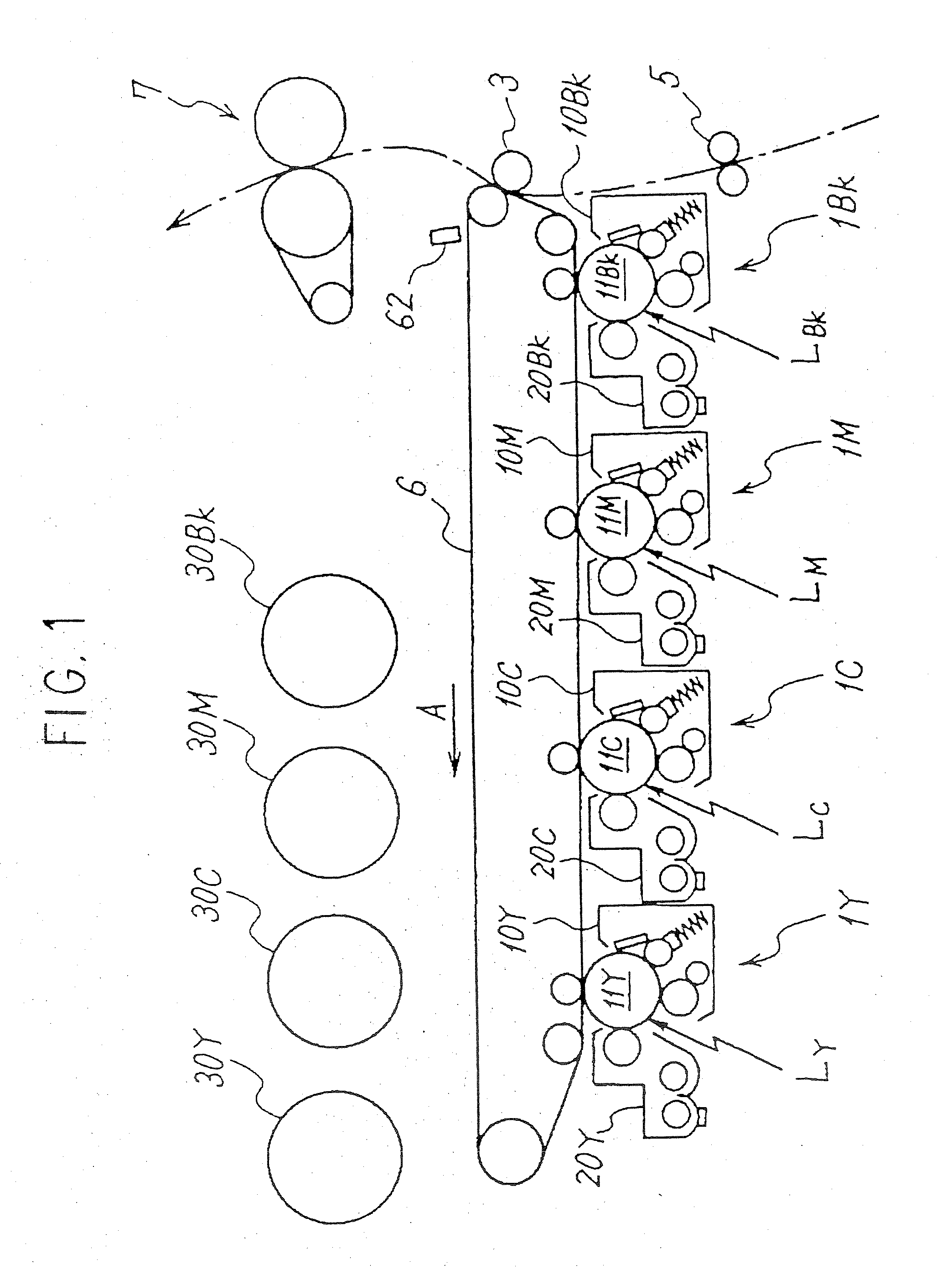
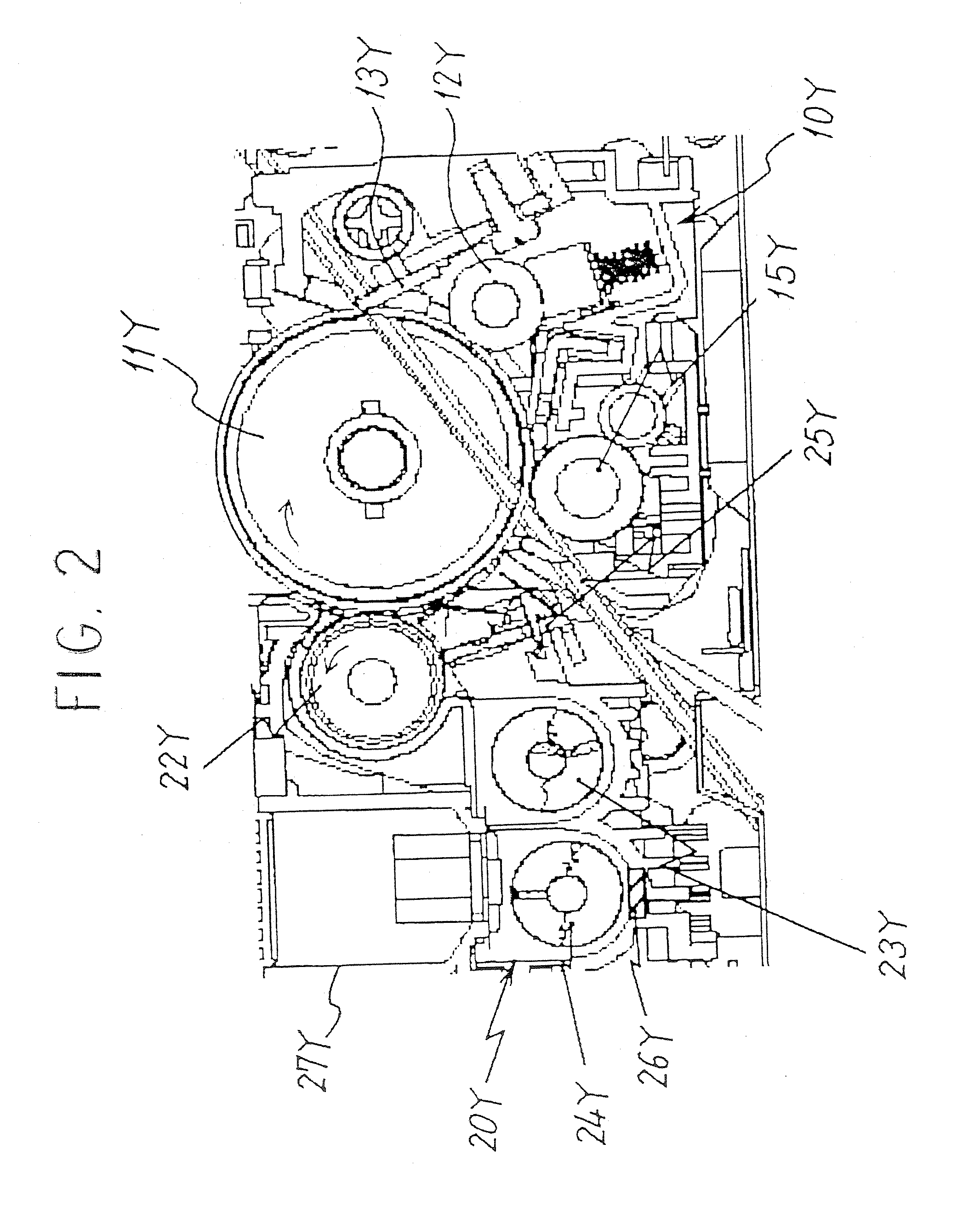
[0025]FIG. 1 shows the schematic configuration of the main part of a laser printer pertaining to the present embodiment. The laser printer comprises four sets of imaging means 1Y, 1C, 1M, 1BK (hereinafter the annotated symbols Y, C, M, BK are used to denote yellow, cyan, magenta and black members respectively) for forming images of the colors magenta (M), cyan (C), yellow (Y) and black (BK) arranged in order from the upstream side in the direction of movement of the surface of an intermediate transfer belt 6 serving as an intermediate transfer member (direction of the arrow A in the drawing). The imaging means 1Y, 1C, 1M, 1BK each comprise photoreceptor units 10Y, 10C, 10M, 10BK having drum-like photoreceptors 11Y, 11C, 11M, 11BK serving as latent im...


PUM


Abstract

An image forming apparatus in which a predetermined image density can be obtained by correcting a toner density control target value without consuming toner. The output The output value Vt of the magnetic permeability sensor and the target output value Vtref are compared, and the toner density is controlled by controlling a powder pump on the basis of the comparative result thereof so that the output value Vt approximates the target output value Vtref. In addition, the target output value Vtref is corrected on the basis of the detected result of the image coverage ratio so as to maintain a predetermined development potential of the development apparatus. By virtue of this, even when image forming that involves a significant change in the toner replacement amount in the development apparatus is performed, for example, even when an image of high image coverage ratio is output, the toner density is adjusted to maintain the development capability at a constant, and a predetermined image density is ensured. Moreover, because the image coverage ratio can be detected without consuming toner, toner does not need to be consumed when the target output value Vtref is corrected.

Description

BACKGROUND OF THE INVENTION [0001] 1. Field of the Invention [0002] The present invention relates to an image forming apparatus such as a copier, a printer and a facsimile device, and more particularly relates to an image forming apparatus that performs image formation employing a two-component developer comprising a toner and a magnetic carrier. [0003] 2. Description of the Related Art [0004] Two-component development systems in which a two-component developer (hereinafter referred to simply as “developer”) comprising a toner and a magnetic carrier is carried on a developer carrier and in which development is carried out as a result of a magnetic brush being formed from the developer by magnetic poles provided within the developer carrier and a latent image on a latent image carrier being rubbed by the magnetic brush are widely known in the prior art. Two-component development systems are being widely utilized because of the simplicity of coloring they afford. When the toner densit...

Claims


Application Information

Patent Timeline
Patent Type & Authority Applications(United States)
IPC IPC(8): G03G15/08
CPCG03G15/5041G03G15/0853G03G15/0849
Inventor TAKEUCHI, NOBUTAKAKATO, SHINJIHASEGAWA, SHINFUJIMORI, KOUTATANAKA, KAYOKOHIRAYAMA, YUJIENAMI, TAKASHIKOBAYASHI, KAZUMISHIMIZU, KIICHIROU
Owner RICOH KK
Why Eureka
Try Eureka