Electronic firing systems and methods for firing a device

a technology of electronic firing system and device, applied in the direction of fuse connector, ammunition fuze, weapons, etc., can solve the problems of unfavorable careful and considered use of such devices, and the firing system is not without its problems

Inactive Publication Date: 2007-06-07
BATTELLE ENERGY ALLIANCE LLC
View PDF17 Cites 40 Cited by
  • Summary
  • Abstract
  • Description
  • Claims
  • Application Information

AI Technical Summary

Benefits of technology

[0008] Also disclosed is an embodiment of an electronic firing system that includes an electrical energy storage device and a charging system for charging said electrical energy storage device with electrical energy. A firing circuit operatively connected to the electrical energy storage device is operable to electrically connect the electrical energy storage device to a device to be fired. A control system operatively connected to the charging system operates the charging system in response to a user-initiated command.
[0009] A method for firing a device may inc...

Problems solved by technology

Unfortunately, however, such firing systems are not without their problems.
However, if the selected countdown time is relatively long, such a control schedule means that the electrical energy storage device may be charged for a time period that is considerably longer than the countdown time.
Consequently, the firing system will be capable of initiating the device well in advance of the desired time, which can lead to ...

Method used


Image

  • Electronic firing systems and methods for firing a device
  • Electronic firing systems and methods for firing a device
  • Electronic firing systems and methods for firing a device

Examples


Embodiment Construction

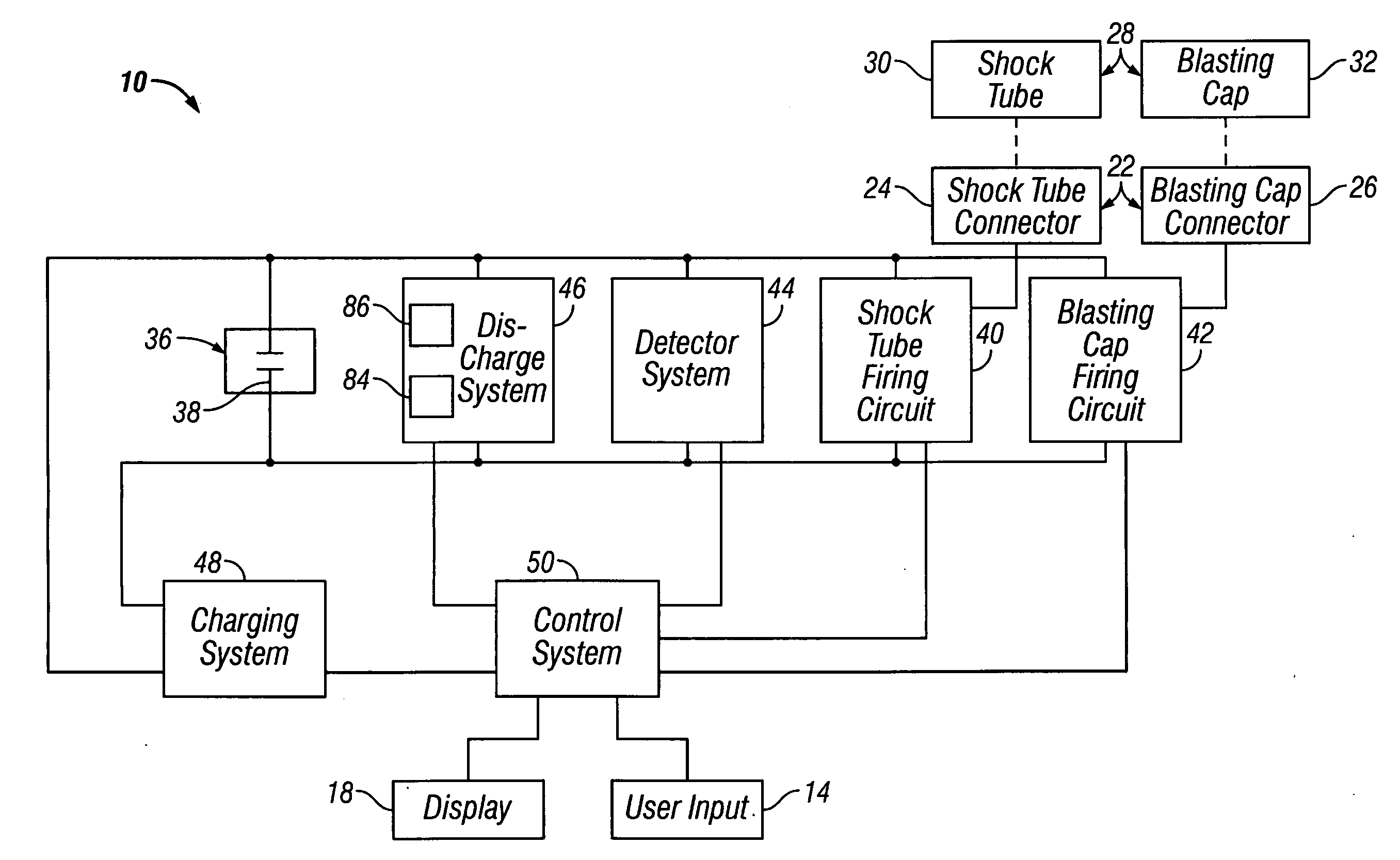
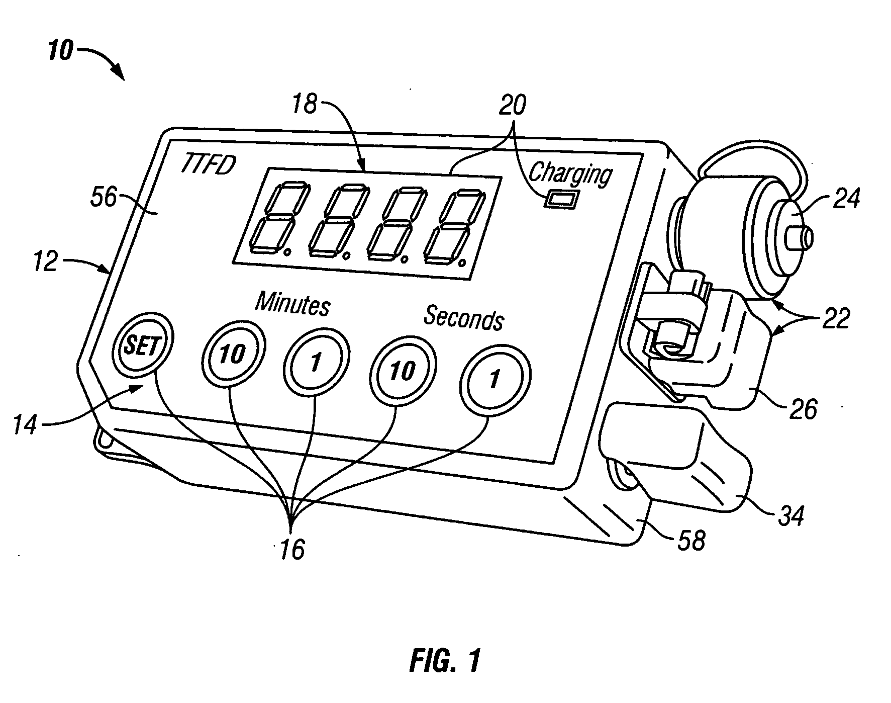
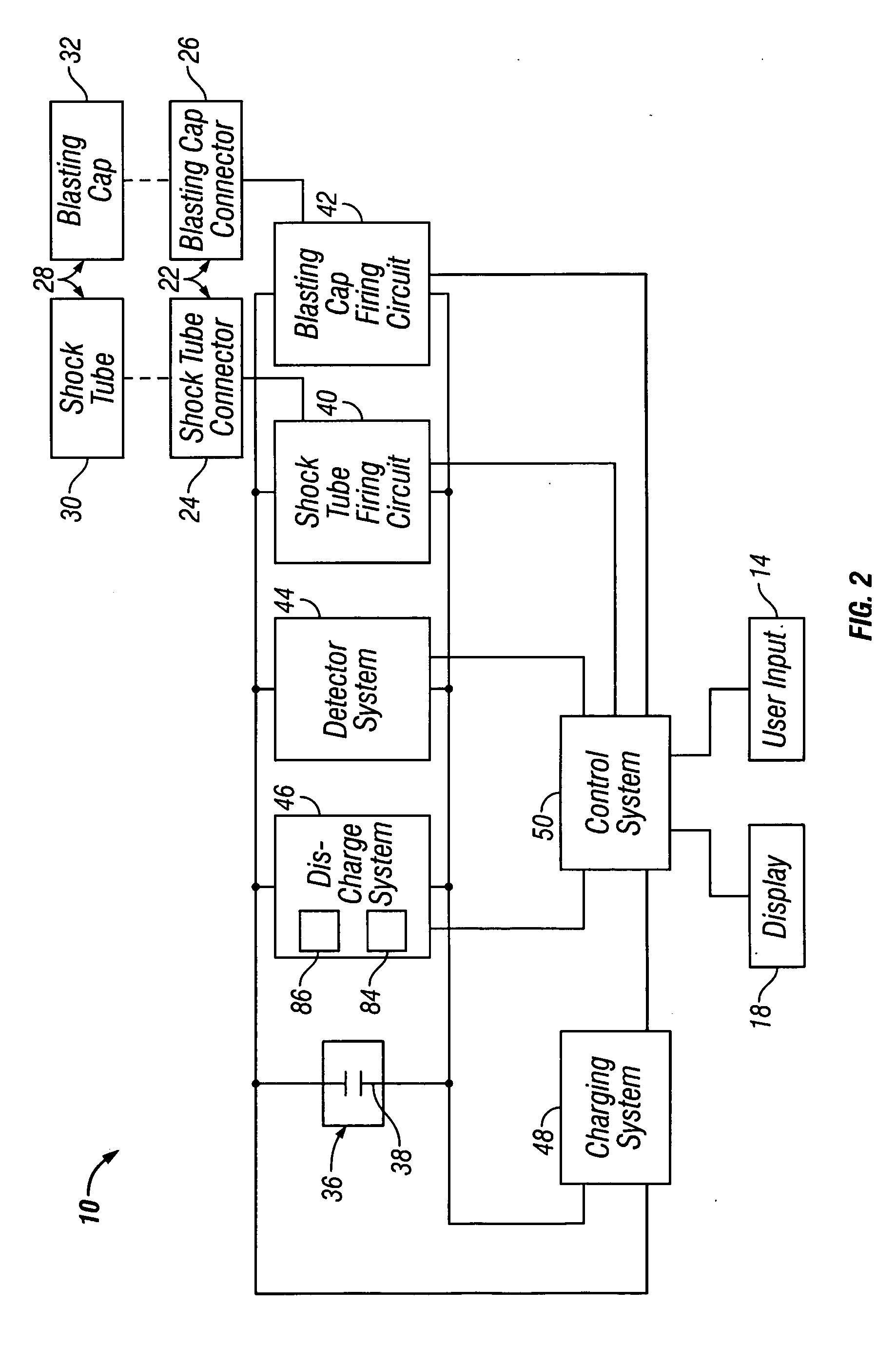
[0018] One embodiment of an electronic firing system 10 is best seen in FIGS. 1 and 2 and may comprise a number of systems and components operatively associated with a housing 12. For example, in one embodiment, the housing 12 of electronic firing system 10 may be provided with a user input system 14 comprising one or more keys 16, and a display system 18 comprising an LED display 20. The electronic firing system 10 may also be provided with one or more output terminals or connectors 22, such as shock tube connector 24 and blasting cap connector 26, to allow a device to be fired 28 (illustrated schematically in FIG. 2), such as a shock tube 30 or a blasting cap 32 (both of which are also illustrated schematically in FIG. 2) to be connected to the electronic firing system 10. The electronic firing system 10 may also be provided with an arm key 34 to allow the electronic firing system 10 to be operated, armed, and disarmed in accordance with the teachings provided herein.

[0019] Refer...


PUM


Abstract

An electronic firing system may include a first firing circuit and a second firing circuit. A detection system operatively associated with the first and second firing circuits detects whether a device to be fired is connected one of the first and second firing circuits. The electronic firing system actuates either of said first and second firing circuits to which is connected the device to be fired.

Description

CONTRACTUAL ORIGIN OF THE INVENTION [0001] The United States Government has certain rights in the invention pursuant to Contract No. DE-AC07-051D14517 between the United States Department of Energy and Battelle Energy Alliance.TECHNICAL FIELD [0002] This invention relates to initiating circuits in general and more specifically to methods and apparatus for the time-delayed initiation of explosive devices. BACKGROUND [0003] Numerous types of firing devices and systems have been developed and are being used that are suitable for firing or initiating a wide range of explosive devices, such as, for example, shock tubes and blasting caps. A typical firing system is provided with an electrical energy storage device, such as a capacitor, which stores the electrical energy needed to initiate or fire the device. Many such firing devices are also provided with a delay or a countdown circuit that may be set by a user to delay the initiation (i.e., firing) of the device for some period of time a...

Claims


Application Information

Patent Timeline
IPC IPC(8): C06C5/06
CPCF42D1/043F42D1/045F42D1/05
Inventor FRICKEY, STEVEN J.SVOBODA, JOHN M.
Owner BATTELLE ENERGY ALLIANCE LLC
Why Eureka
Try Eureka