Airbag apparatus for vehicle

a technology for airbags and vehicles, applied in the direction of vehicle components, pedestrian/occupant safety arrangements, vehicular safety arrangments, etc., can solve the problem of proportional deterioration of the function of straps, and achieve the effect of improving the rate at which airbags are developed, easy cleaving, and increased protection rang

Inactive Publication Date: 2007-06-07
NIHON PLAST CO LTD
View PDF7 Cites 14 Cited by
  • Summary
  • Abstract
  • Description
  • Claims
  • Application Information

AI Technical Summary

Benefits of technology

[0011] In this case, the front end or the rear end of the airbag provided in the folded condition includes the pulled-out section. Thus, an oblique path from the front end of the airbag in the stored condition to the fixed point of the pillar can be reached by the total length of the strap and the pulled-out section. Thus, the length of the strap itself only has to have a short length. In the developed condition of the airbag, the strap can further draw the position of the front end of the airbag to the front side, thereby providing an increased protection range by the airbag.
[0012] A base end of the roll section in the airbag preferably includes a pair of double-lapped inflating sections that cover the roll section. This structure allows the double-lapped inflating sections in the developed condition to inflate to push the roll section in a downward direction, thus improving a rate at which the airbag is developed.
[0013] The airbag in the folded condition is preferably stored in a wrap cylinder that can be easily cleaved when the airbag is inflated. By this structure, the wrap cylinder maintains the folded condition of the airbag, thus providing an easy handling of the airbag prior to or in the installation of the airbag to the vehicle body. Furthermore, the wrap cylinder that can be easily cleaved allows the airbag during the inflation to be easily developed in a downward direction.

Problems solved by technology

This causes a proportional deterioration of the function of the strap for preventing the position of the front end of the airbag from being withdrawn.

Method used


Image

  • Airbag apparatus for vehicle
  • Airbag apparatus for vehicle
  • Airbag apparatus for vehicle

Examples


Embodiment Construction

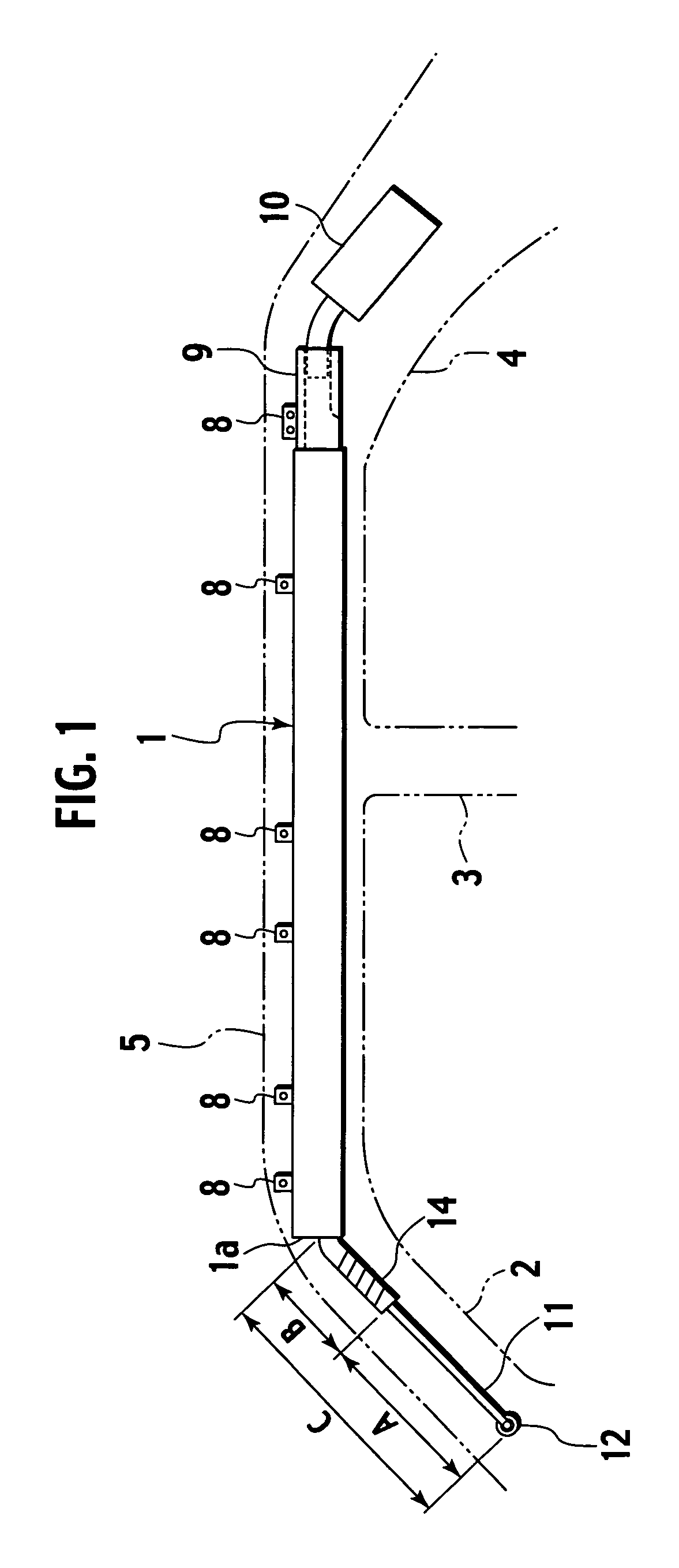
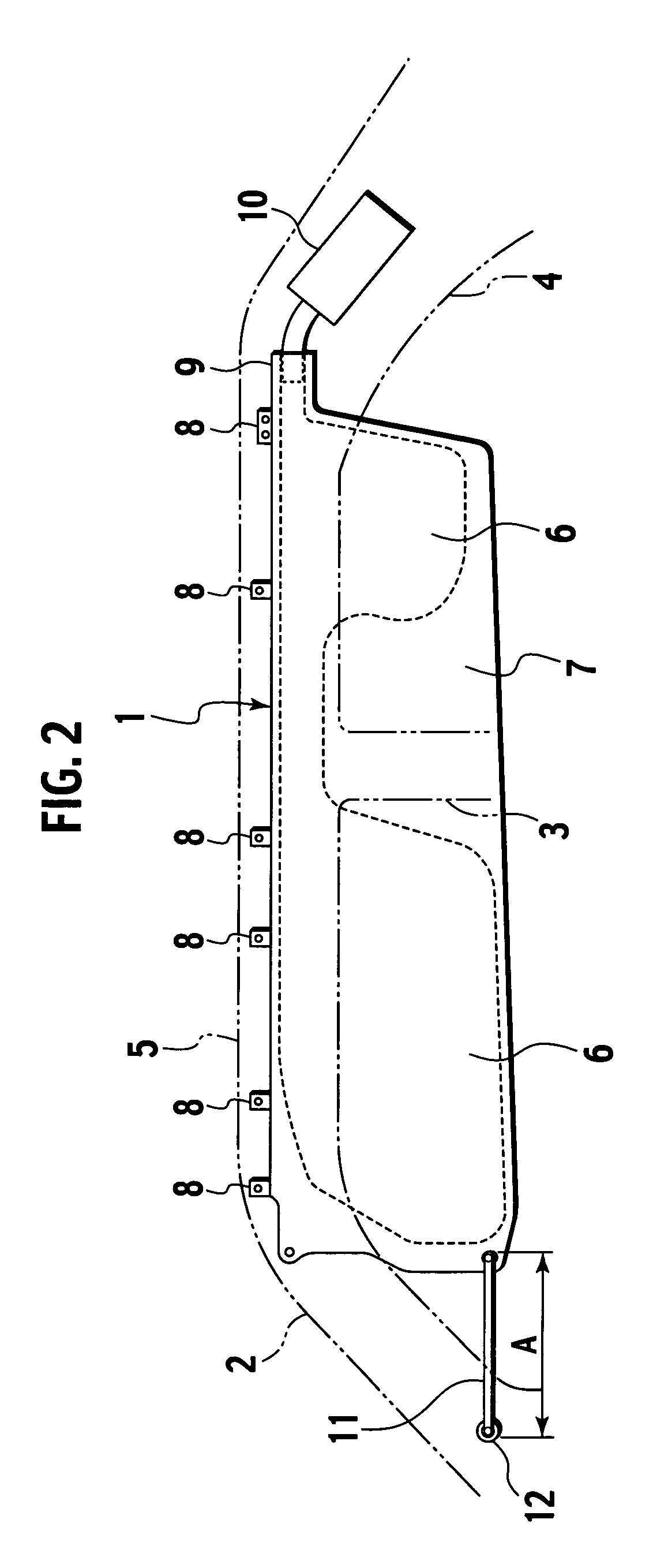
[0027] Hereinafter, embodiments of the present invention will be described with reference to the drawings. FIG. 1 and FIG. 2 illustrate an upper part of an automobile seen from an inner side of a vehicle interior. FIG. 1 shows the condition in which an airbag 1 is not yet developed. FIG. 2 shows the condition in which the airbag 1 is developed. A reference numeral 2 denotes a front pillar, a reference numeral 3 denotes a center pillar, and a reference numeral 4 denotes a rear pillar. At the upper parts of the respective pillars 2, 3, and 4, a side roof rail (vehicle body upper part) 5 is provided along a front-to-end direction.

[0028] As shown in FIG. 2, the airbag 1 has a long bag-like shape extending in a front-to-end direction. The airbag 1 is composed of an inflation section 6 divided by a stitching line and a non-inflation section 7 at the outer side of the inflation section 6. An upper end of the airbag 1 includes a plurality of tabs 8. The tab 8 is fixed to the side roof rail...


PUM


Abstract

In an airbag provided in a folded condition, a front end of the airbag includes a pulled-out section provided by pulling out the end of the airbag. In the airbag in a stored condition, an oblique path from a front end of the airbag to a fixed point of a front pillar can be reached by the pulled-out section. In the developed condition of the airbag, the pulled-out section can further draw the position of the front end of the airbag to the front side, thereby providing an increased protection range by the airbag.

Description

BACKGROUND OF THE INVENTION [0001] 1. Field of the Invention [0002] The present invention relates to an airbag apparatus for a vehicle. [0003] 2. Description of Related Art [0004] An upper part of a vehicle body of an automobile includes an airbag that protects, when the automobile is subjected to a side impact, the head of an occupant by being developed in a downward direction. A front end of a lower end of the airbag is joined to one end of a strap. The other end of the strap is joined to a fixed point of a front pillar. In some structures, a rear end of an airbag may be connected to a rear pillar by a strap. [0005] When an airbag is developed, a front end of the airbag is connected to a front pillar by a substantially horizontal strap to prevent the front end of the airbag in the developed condition from being withdrawn. The airbag is stored in a vehicle body in a folded condition in which the airbag is wound from the lower end. A strap is provided toward the fixed point in an ob...

Claims


Application Information

Patent Timeline
Patent Type & Authority Applications(United States)
IPC IPC(8): B60R21/213B60R21/237B60R21/20B60R21/201B60R21/2338
CPCB60R21/201B60R21/213B60R21/232B60R21/237
Inventor YOSHIDA, MITSUHIRO
Owner NIHON PLAST CO LTD
Why Eureka
Try Eureka