Ergonomic control apparatus for a patient support apparatus

a technology of patient support and control apparatus, which is applied in the direction of instruments, tables, transportation and packaging, etc., can solve the problems of health care providers losing sight of the control module, affecting the control of the bed controller, and affecting the patient's comfor

Active Publication Date: 2007-06-14
STRYKER CORP
View PDF63 Cites 96 Cited by
  • Summary
  • Abstract
  • Description
  • Claims
  • Application Information

AI Technical Summary

Benefits of technology

[0009] An object of the present invention is to provide a an ergonomic control apparatus for a patient support apparatus. In accordance with an aspect of the present invention, there is provided control apparatus for use with a patient support apparatus, said control apparatus comprising: a housing; a control module adapted for connection to the housing, said control module operatively coupled to the patient support apparatus and configured for controlling one or more functions associated with the patient support apparatus; and a coupling device movably connecting the housing to the patient support apparatus, said coupling device providing movement of the housing in one or more dimensions relative to the patient support apparatus; wherein the control apparatus can be positioned in order that a user interface associated therewith is accessible to an operator independent of configuration of the patient support apparatus.

Problems solved by technology

Traditionally, when a bed is positioned or articulated to meet a specific treatment or patient need, access to the controller of the bed can be an issue.
Often, access to the controller is encumbered by other parts of the bed, and can often only be achieved with difficulty due to the relative position of the health care provider, and therefore clear vision of the controls or status of bed functions by the health care provider can be compromised.
In conventional known medical bed designs, where the foot section of the bed must be lowered, the health care provider might lose sight of the control module and see his / her accessibility thereto reduced because of the angle and relative position of the foot section.
In such a case, it is also possible that the health care provider may not be able to use or control some or all the functions of the bed when the control module is situated too close to the floor or in a position in which it is ergonomically difficult to properly operate.
The disclosed bed requires a support panel attached to the base of the bed by a sliding movement, limiting the types of beds it can be attached to.
The modular control unit in the disclosure is also only pivotally adjustable to two positions, a use position and a storage position, and is not always readily accessible or visible since its position is interdependent on the position of the base of the footboard or the second barrier.
U.S. patent application Ser. No. 11 / 040,272 (Publication No. 2005 / 0188462) discloses a controller embedded in a siderail of a medical bed, or in a means mounted to the bed for inhibiting egress from the bed, but with the limitation that the inhibiting means being movable between a raised position and a lowered position.
Also, the disclosed controller only has two stationary positions: the stored position and the deployed position, often resulting in a poor ergonomic position for operation of the controller.
In addition, the controller changes position when the structure to which it is attached is moved, therefore diminishing the accessibility and visibility of the control module.

Method used


Image

  • Ergonomic control apparatus for a patient support apparatus
  • Ergonomic control apparatus for a patient support apparatus
  • Ergonomic control apparatus for a patient support apparatus

Examples


Embodiment Construction

Definitions

[0042] As used herein, the term “about” refers to a + / −10% variation from the nominal value. It is to be understood that such a variation is always included in any given value provided herein, whether or not it is specifically referred to.

[0043] Unless defined otherwise, all technical and scientific terms used herein have the same meaning as commonly understood by one of ordinary skill in the art to which this invention belongs.

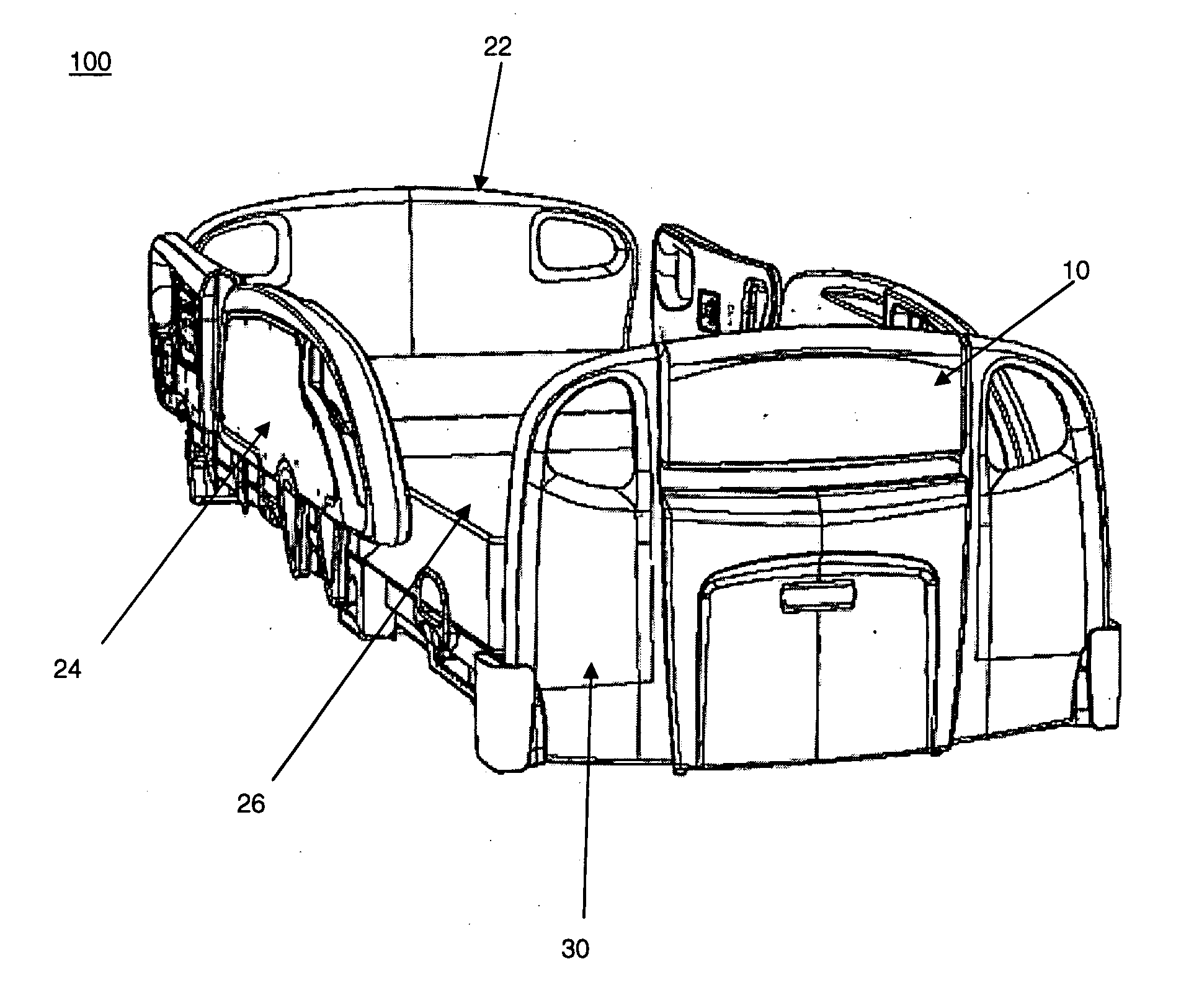
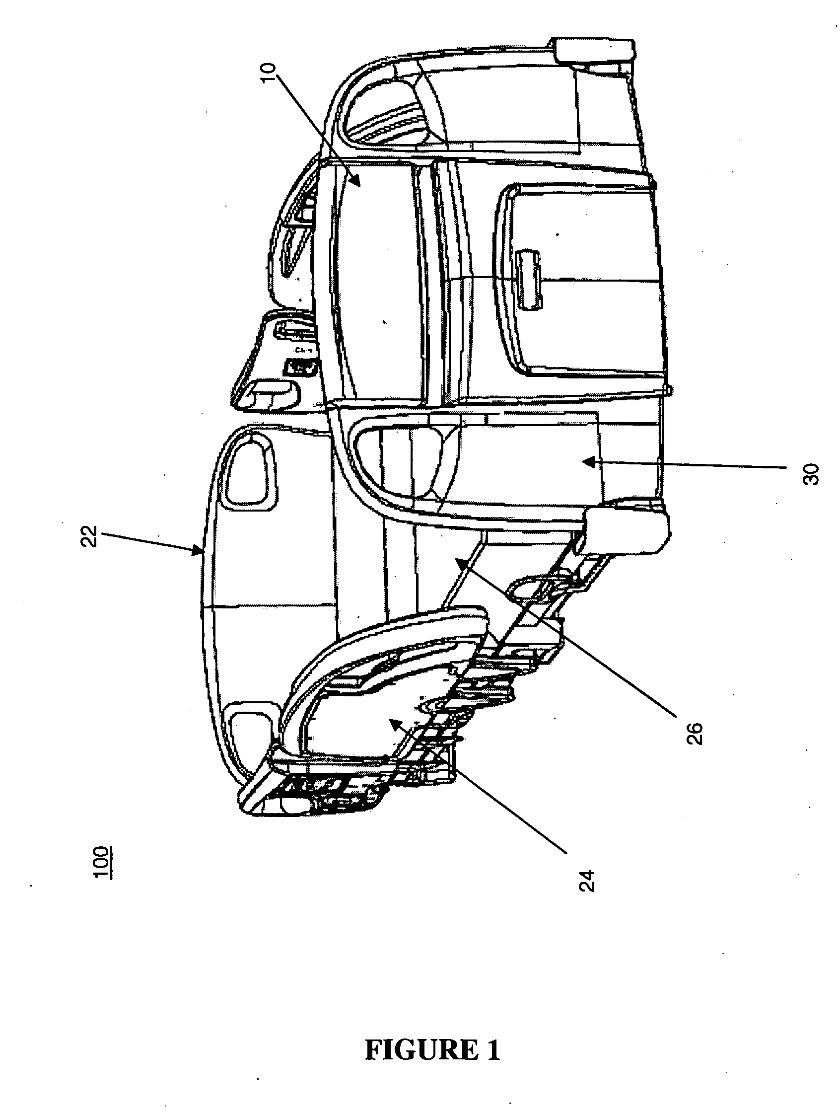
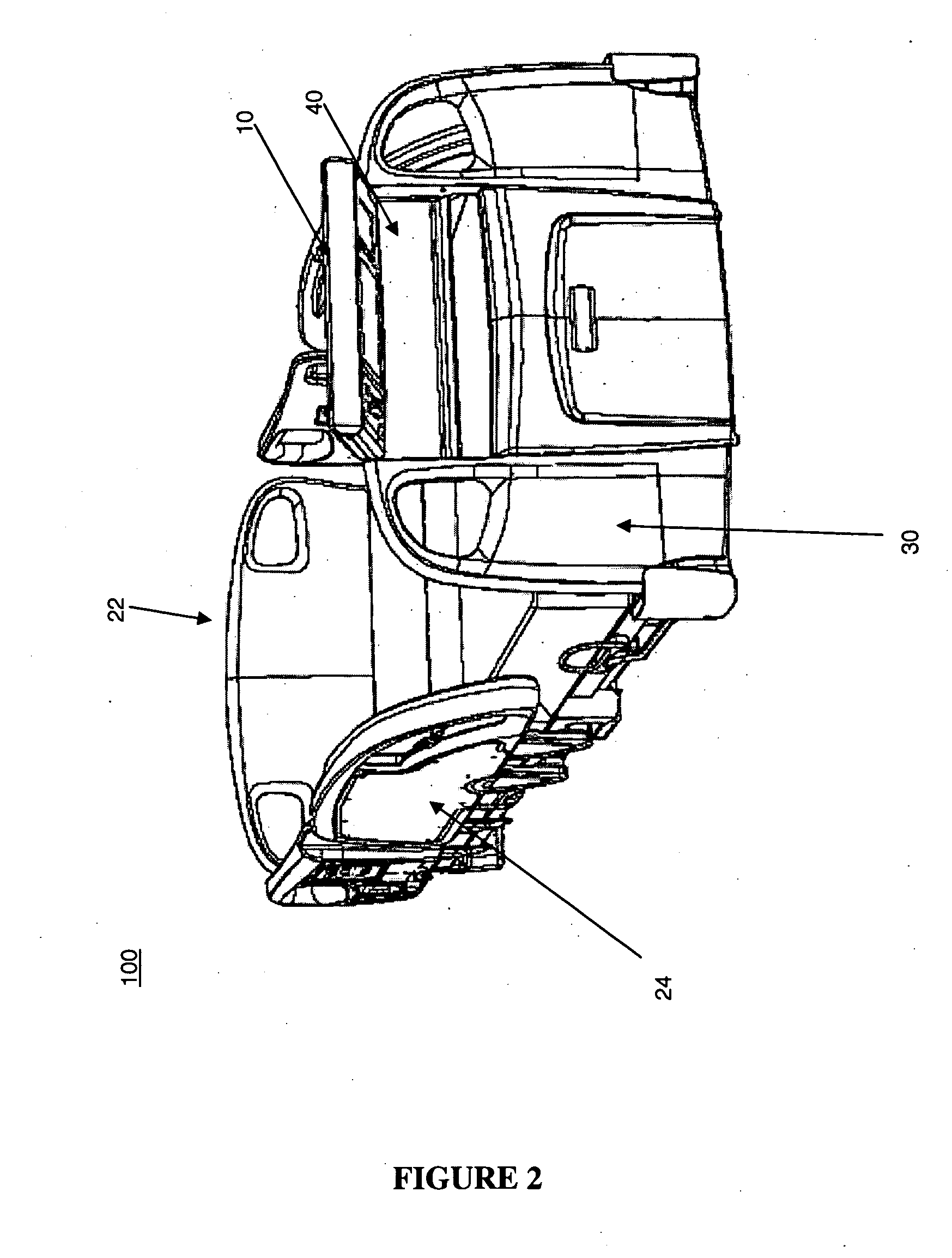
[0044] The present invention will thus be described in association with a patient support apparatus that includes a frame system and a mattress or other lying surface. The frame system includes a base frame supported on the floor, for example by a plurality of caster wheels, an intermediate frame supported by an elevation system comprising lift arms configured to raise and lower the intermediate frame relative to the base frame, and a deck support connected to the intermediate frame. The deck support comprising a head or fowler section, a seat ...


PUM


Abstract

The present invention provides a control apparatus that can be ergonomically and movably connected to a patient support apparatus. The control apparatus comprises a control module which is operatively coupled to the patient support apparatus and can provide a means for controlling the plurality of patient support apparatus functions. The control module is adapted for connection to a housing and the housing is movably connected to the patient support apparatus by a coupling device. The coupling device enables the relative movement of the housing and as such the control module relative to the patient support apparatus. In this manner access to the control module, and therefore to the functionality of the patient support apparatus, can be provided independent of the configuration of the patient support apparatus.

Description

FIELD OF THE INVENTION [0001] The present invention pertains to the field of patient support apparatuses. More particularly, the present invention relates to a control apparatus for use with patient support apparatus. BACKGROUND [0002] Medical and hospital beds for patient support are known in the art. Typically, such patient support apparatuses are used to provide a support surface for treatment, recuperation or rest of patients. Many such patient support apparatuses include a frame, a support surface held by the frame, a mattress, siderails configured to block egress of a patient from the mattress, and a controller configured to control one or more features of the bed. [0003] In order to accommodate various needs and treatments, medical and hospital beds are required to be versatile and must be articulated as much as possible. Traditionally, when a bed is positioned or articulated to meet a specific treatment or patient need, access to the controller of the bed can be an issue. Of...

Claims


Application Information

Patent Timeline
Patent Type & Authority Applications(United States)
IPC IPC(8): A47B7/02
CPCA61G7/018A61G7/05A61G7/0506A61G2203/16A61G2203/20
Inventor LEMIRE, GUYDIONNE, JEAN-PAULMORIN, MARCOSOUI WAN FONG, DAVID KIMCANTIN, NICOLAS
Owner STRYKER CORP
Why Eureka
Try Eureka