
Developing System and Image Forming Apparatus Using the Same

Inactive Publication Date: 2007-06-21
SEIKO EPSON CORP
View PDF6 Cites 17 Cited by
  • Summary
  • Abstract
  • Description
  • Claims
  • Application Information

AI Technical Summary

Benefits of technology

[0010] Accordingly, the object of the present invention is to provide a structure capable of flexibly supplying carrier to developer containers to maintain the conditions of developers in the developer containers constant so as to achieve stable image formation.
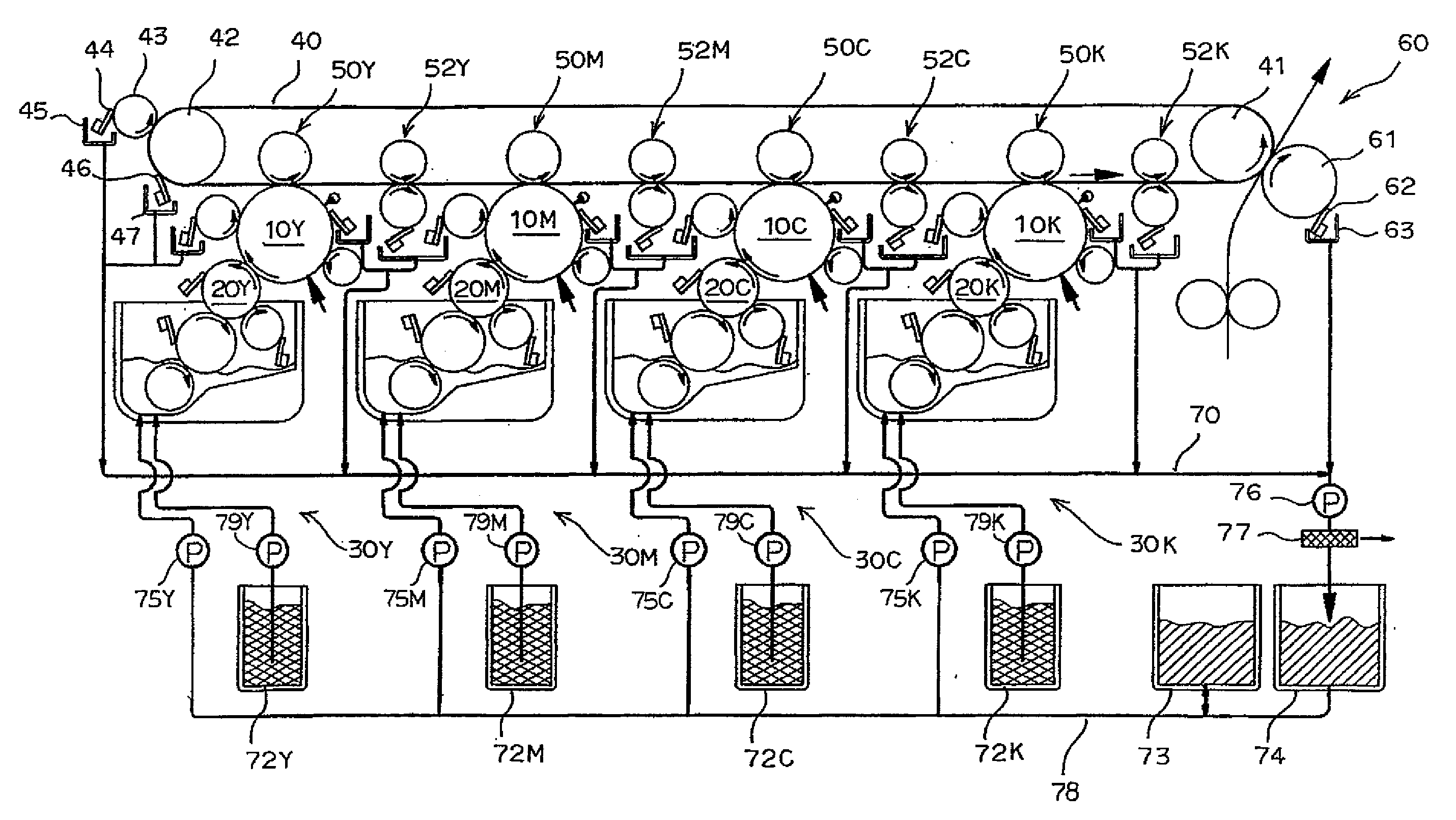
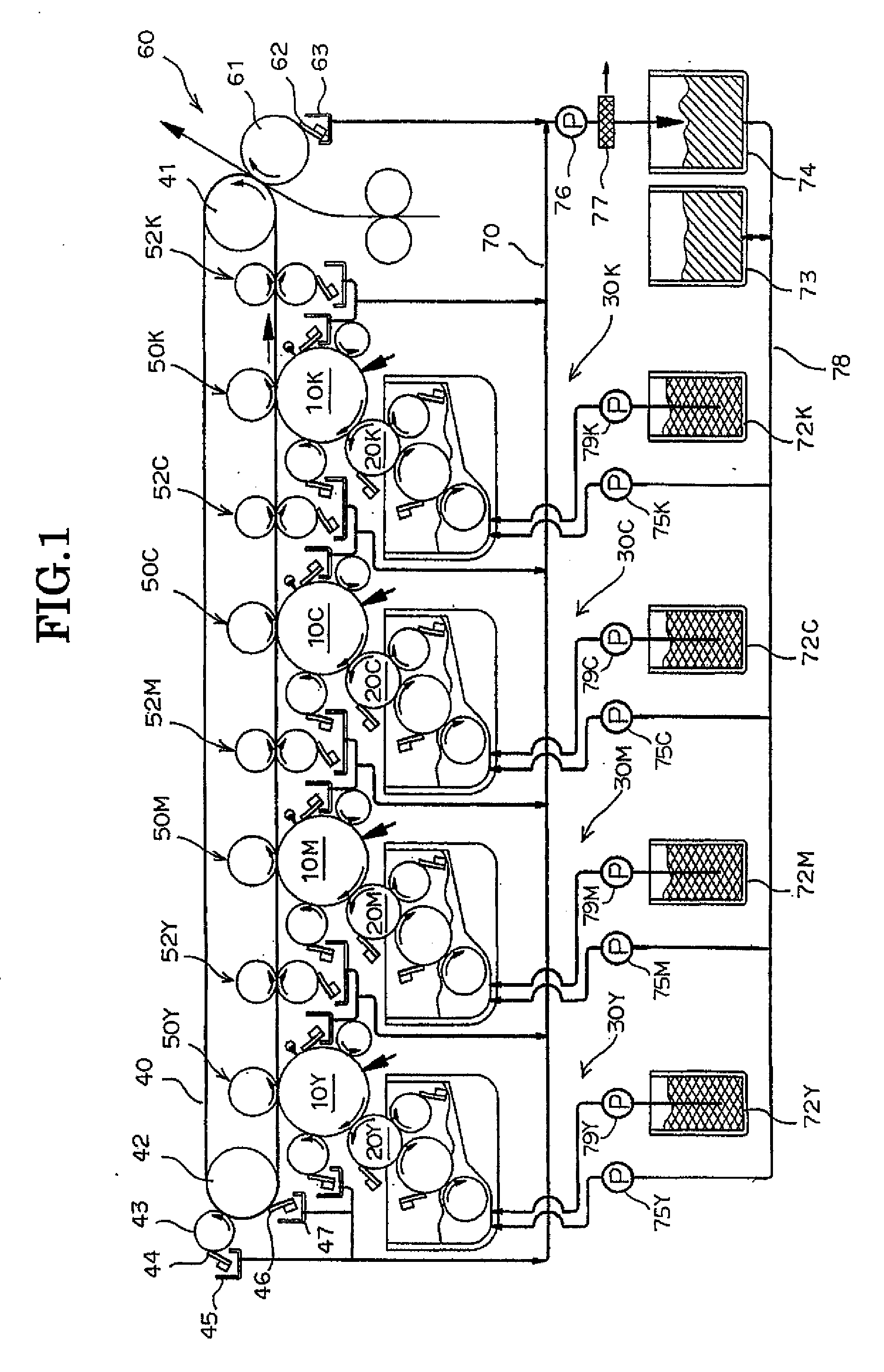
[0028] The apparatus according to the invention has a structure capable of flexibly supplying carrier to developer containers. Specifically, developers are collected to a buffer tank from image carrier squeezing devices, image carrier cleaning devices, an intermediate transfer squeezing device, an intermediate transfer cleaning device, and a secondary transfer roller cleaning device and then carrier of the collected developers can be distributed from the buffer tank to a plurality of developer containers. Therefore, the toner weight ratios in the developer containers can be controlled to be constant, thereby achieving stable image formation.

Problems solved by technology

Though the carrier liquid is a necessary ingredient for the toner conservation, the toner transport, the development, and the transfer process as mentioned above, the carrier liquid adheres also to non-imaging regions and the excess carrier liquid after development may cause deterioration of transfer.

Method used


Image

  • Developing System and Image Forming Apparatus Using the Same
  • Developing System and Image Forming Apparatus Using the Same
  • Developing System and Image Forming Apparatus Using the Same

Examples


Embodiment Construction

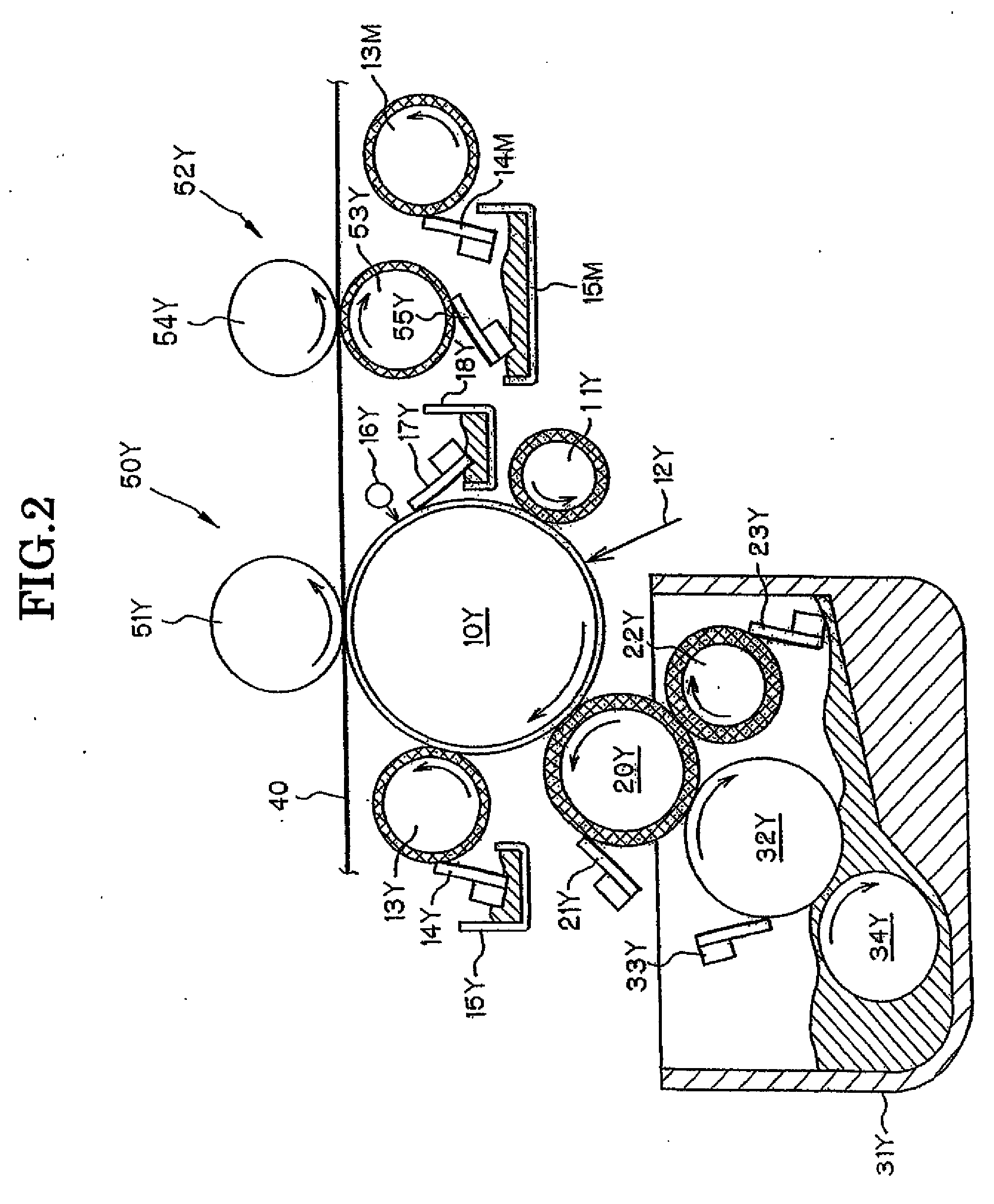
[0032] Hereinafter, embodiments of the invention will be described with referred to the attached drawings. FIG. 1 is an illustration showing main components composing a developing system according to an embodiment of the invention and FIG. 2 is a sectional view showing main components of an image forming section, a developing unit, and an intermediate transfer member squeezing device. As for the mage forming sections, the developing units, and the intermediate transfer member squeezing devices for respective colors i.e. yellow (Y), magenta (M), cyan (C), and black (K), the same components for the respective colors are marked with the same numerals with respective marks Y, M, C, K for indicating the respective colors. Among these, the image forming section, the developing unit, and the intermediate transfer member squeezing device for yellow (Y) are shown in FIG. 2. Hereinafter, detail description about the image forming section, the developing unit, and the intermediate transfer mem...


PUM


Abstract

A developing system comprises: a plurality of image carriers; a plurality of developing devices for developing electrostatic latent images, formed on the plurality of image carriers, with respective liquid developers of different colors of which carrier is nonvolatile solvent; and developer collecting means which are disposed at a plurality of locations for collecting excess developers, wherein the developing devices have developer containers, respectively. The developing system further comprises a carrier storing tank for distributing the carrier to the respective developer containers.

Description

CROSS-REFERENCE TO RELATED APPLICATIONS [0001] This application is based on Japanese Patent Applications No. 2005-366165 filed Dec. 20, 2005, No. 2005-366166 filed Dec. 20, 2005, and No. 2005-366167 filed Dec. 20, 2005, the entire contents including specifications, drawings, and abstracts of which are incorporated herein by reference. BACKGROUND [0002] 1. Technical Field [0003] The present invention relates to a developing system comprising a plurality of image carriers, a plurality of developing devices for developing electrostatic latent images formed on the plurality of image carriers with respective developers of different colors of which carrier is nonvolatile solvent, and a plurality of developer collecting means which are disposed at a plurality of positions to collect excess developers. The present invention also relates to an image forming apparatus using the aforementioned developing system and comprising an intermediate transfer member to which developed toner images are ...

Claims


Application Information

Patent Timeline
IPC IPC(8): G03G15/10
CPCG03G15/095G03G2215/0119
Inventor ARUGA, TOMOEIKUMA, KEN
Owner SEIKO EPSON CORP
Learn More