
Transprinting mechanism and image forming device using the same

A transfer printing and image technology, applied to the electric recording process using the charge pattern, the equipment of the electric recording process using the charge pattern, and the electrography, etc., can solve the problem of delay, non-smooth movement, transfer belt and photosensitive drum Contact separation and other issues, to achieve the effect of precise drive transmission, simple structure, and improved responsiveness

Active Publication Date: 2008-01-02
SHARP KK
View PDF1 Cites 0 Cited by
  • Summary
  • Abstract
  • Description
  • Claims
  • Application Information

AI Technical Summary

Problems solved by technology

[0009] However, in the method using the above-mentioned electromagnetic coil, due to its assembly accuracy and processing accuracy, the action of the cam on the side farther from the electromagnetic coil will be delayed, and it cannot move smoothly, and it is difficult to make the transfer belt and the photosensitive drum contact and separate. Case

Method used


Image

  • Transprinting mechanism and image forming device using the same
  • Transprinting mechanism and image forming device using the same
  • Transprinting mechanism and image forming device using the same

Examples


no. 1 approach

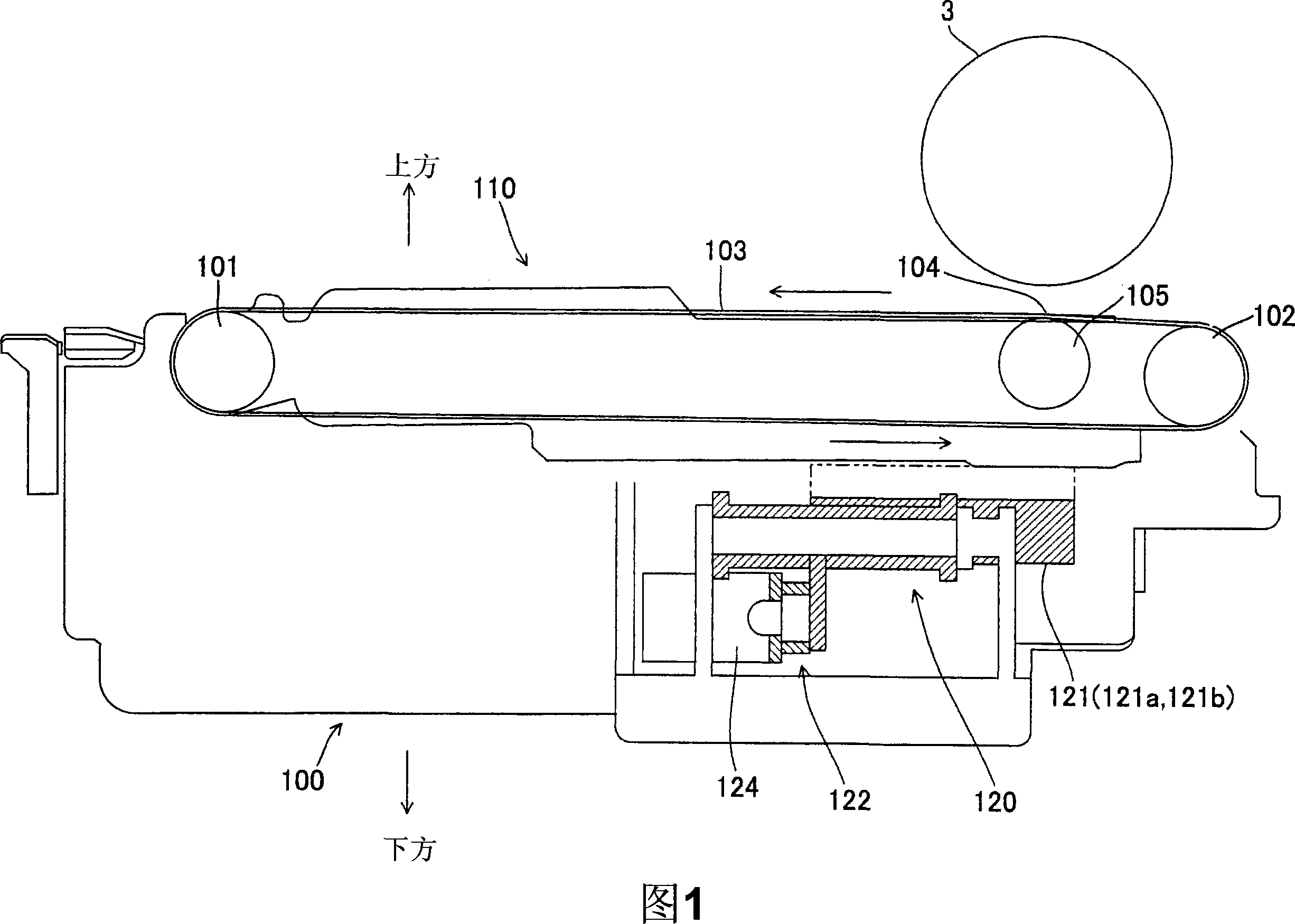
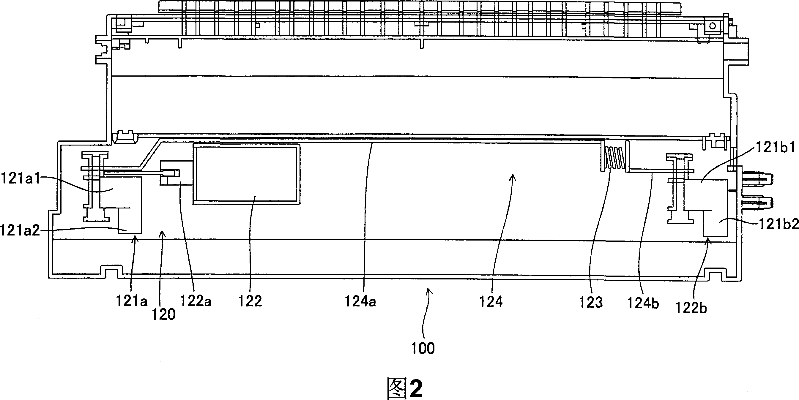
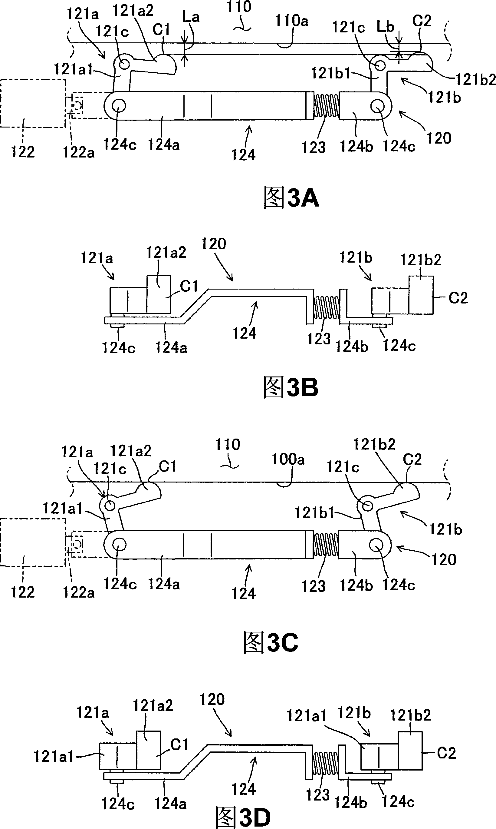
[0048] Hereinafter, an embodiment of the present invention will be described in detail with reference to FIGS. 1 to 6 .

[0049] The transfer mechanism 100 of the present embodiment includes a transfer unit 110 and a belt contact and separation unit 120 ( FIGS. 1 and 2 ). In addition, in FIG. 1 , symbol 3 denotes a photosensitive drum (electrostatic latent image carrier).

[0050] (transfer unit 110)

[0051] The transfer unit 110 includes an endless transfer belt 103 ( FIG. 1 ) that conveys paper (recording medium). The transfer unit 110 transfers the toner image (developer image) developed on the photosensitive drum 3 onto paper conveyed by the transfer belt 103 .

[0052] In addition, the transfer belt 103 may have a structure that does not convey paper. That is, the transfer unit 110 may be configured to directly transfer the toner image developed on the photosensitive drum 3 to the transfer belt 103 .

[0053] The transfer unit 110 is disposed below the photosensitive...

no. 2 approach

[0124] Next, an image forming apparatus 1A equipped with the transfer mechanism 100 of the present invention will be described in detail with reference to the drawings.

[0125] 7 is an explanatory view showing the overall structure of an image forming apparatus employing a transfer mechanism according to a second embodiment of the present invention, and FIG. 8 is a partial detailed view showing the structure of the main body of the image forming apparatus.

[0126] The image forming apparatus 1A of this embodiment is an image forming apparatus that includes an image forming unit 14 , a transfer mechanism 100 , and a fixing unit (fixing mechanism) 6 , and outputs an image according to a print request.

[0127] The image forming unit 14 has a photosensitive drum 3 that forms a developer image (toner) using a developer (toner).

[0128] The transfer mechanism 100 adopts the transfer mechanism of the present invention, and includes the above-mentioned transfer unit 110 and the ab...


PUM


Abstract

A transfer printing mechanism comprising a transfer printing unit with transfer printing belt, and belt contact-separate portion making the transfer printing belt contact-separate with an electrostatic sub-image supporting body by making location of the transfer printing unit displace are provided in the present invention. The belt contact-separate portion comprises: a plurality of transfer printing unit displacing components contacting with transfer printing unit and displacing the transfer printing unit; a plurality of linking components making the transfer printing unit displacing components link; elastic components connecting the linking components; and a driving portion making the transfer printing unit displacing components act by the linking components.

Description

technical field [0001] The present invention relates to a transfer mechanism and an image forming apparatus using the transfer mechanism, in particular to an image forming apparatus applied to copiers, multifunction machines, printers, facsimile machines, etc. using electrophotography and outputting images according to printing requirements A transfer mechanism used and an image forming apparatus using the transfer mechanism. Background technique [0002] The transfer mechanism of the image forming device has the following functions: make the conveyed recording medium (paper) contact with the electrostatic latent image carrier (photosensitive drum), apply a transfer electric field from the back of the paper, and transfer the image on the photosensitive drum to The developed image information (toner image or developer image) is transferred onto paper. [0003] In recent years, development of a belt transfer method using an endless belt as a transfer mechanism has progressed ...

Claims


Application Information

Patent Timeline
Patent Type & Authority Applications(China)
IPC IPC(8): G03G15/16G03G15/00
Inventor 村井宏行泷口俊树增田润也清家俊彦松山和弘
Owner SHARP KK
Learn More