Methods and apparatus for retractable pin friction stir welding and spot welding

Active Publication Date: 2007-07-05
THE BOEING CO
View PDF3 Cites 62 Cited by
  • Summary
  • Abstract
  • Description
  • Claims
  • Application Information

AI Technical Summary

Benefits of technology

[0010] In still another aspect, a friction stir welding apparatus is provided. The welding apparatus includes a rotational assembly having an outer diameter, and a stationary assembly having an inner diameter substantially adjacent

Problems solved by technology

The rotation of the pin against the work piece materials produces a large amount of frictional heating in both the welding pin and the plate.
This heat causes the work piece materials to soften in the vicinity of the rotating pin, which r

Method used


Image

  • Methods and apparatus for retractable pin friction stir welding and spot welding
  • Methods and apparatus for retractable pin friction stir welding and spot welding
  • Methods and apparatus for retractable pin friction stir welding and spot welding

Examples


Embodiment Construction

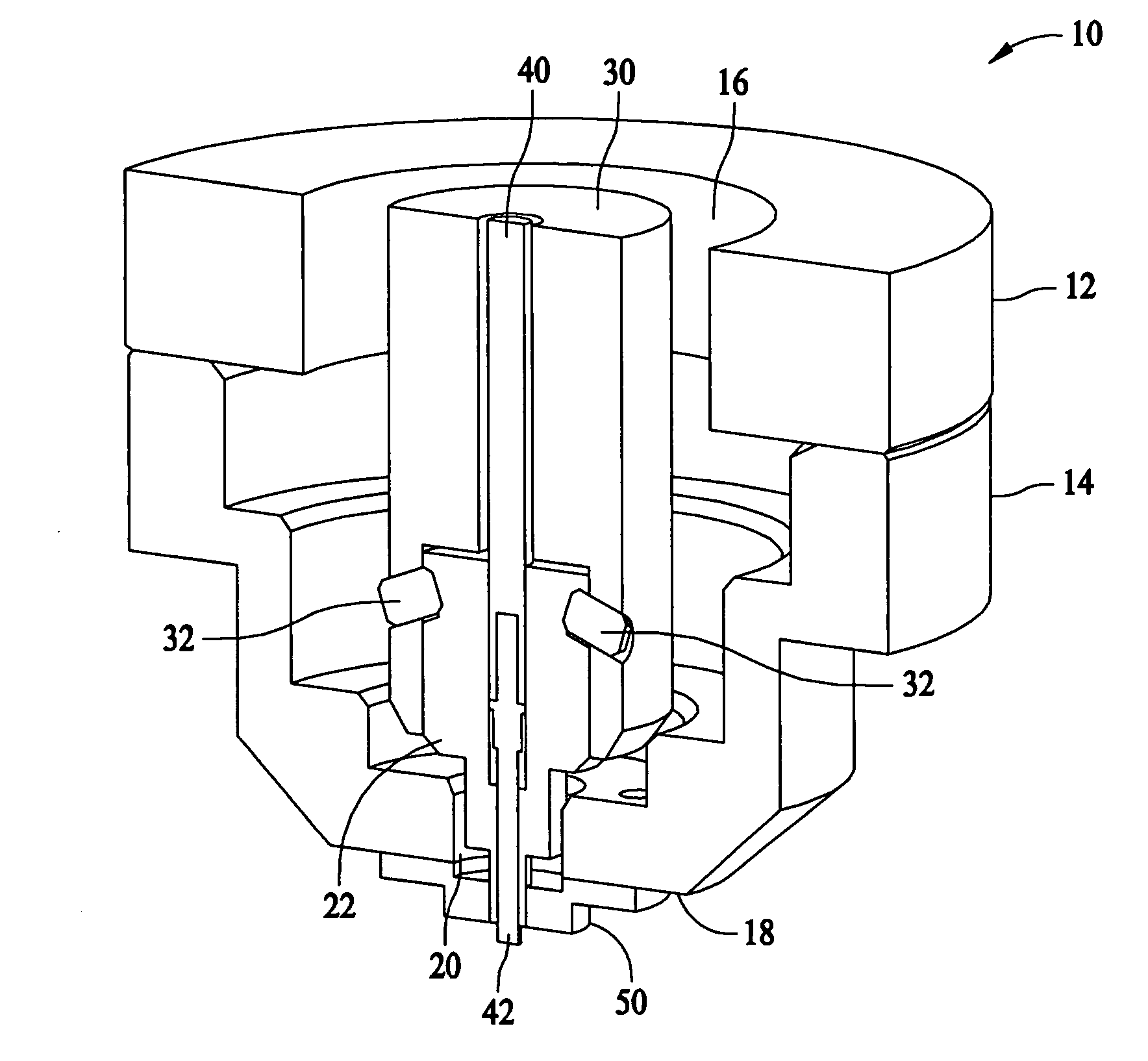
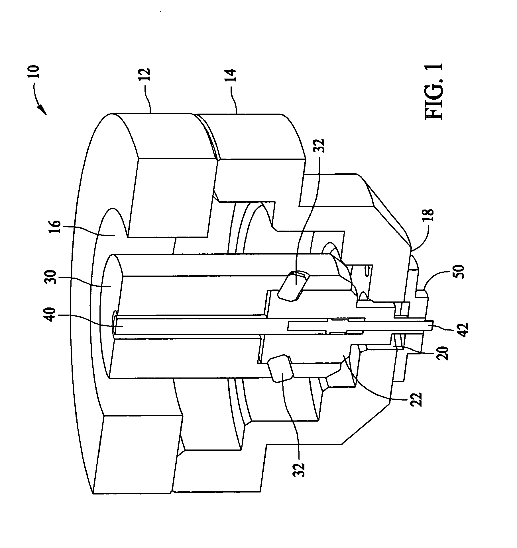
[0020]FIG. 1 is a cross-sectional view of a friction stir spot welding device 10. Spot welding device 10 includes a spindle housing 12 attached to a clamping housing 14. As illustrated in FIG. 1, spindle housing 12 and clamping housing 14 define a cavity 16. Cavity 16 extends through a bottom 18 of clamping housing 14 and defines a bore 20. A shoulder tool 22 is configured to be inserted into bore 20. Shoulder tool 22 is held in place by a shoulder spindle 30 and locking screws 32. Shoulder spindle 30 has a bore therethrough in which is held a pin spindle 40 and a pin tool 42. Pin tool 42 and shoulder tool 22 extend through bore 20 of clamping housing 14 and are retained in place by a clamping anvil 50.

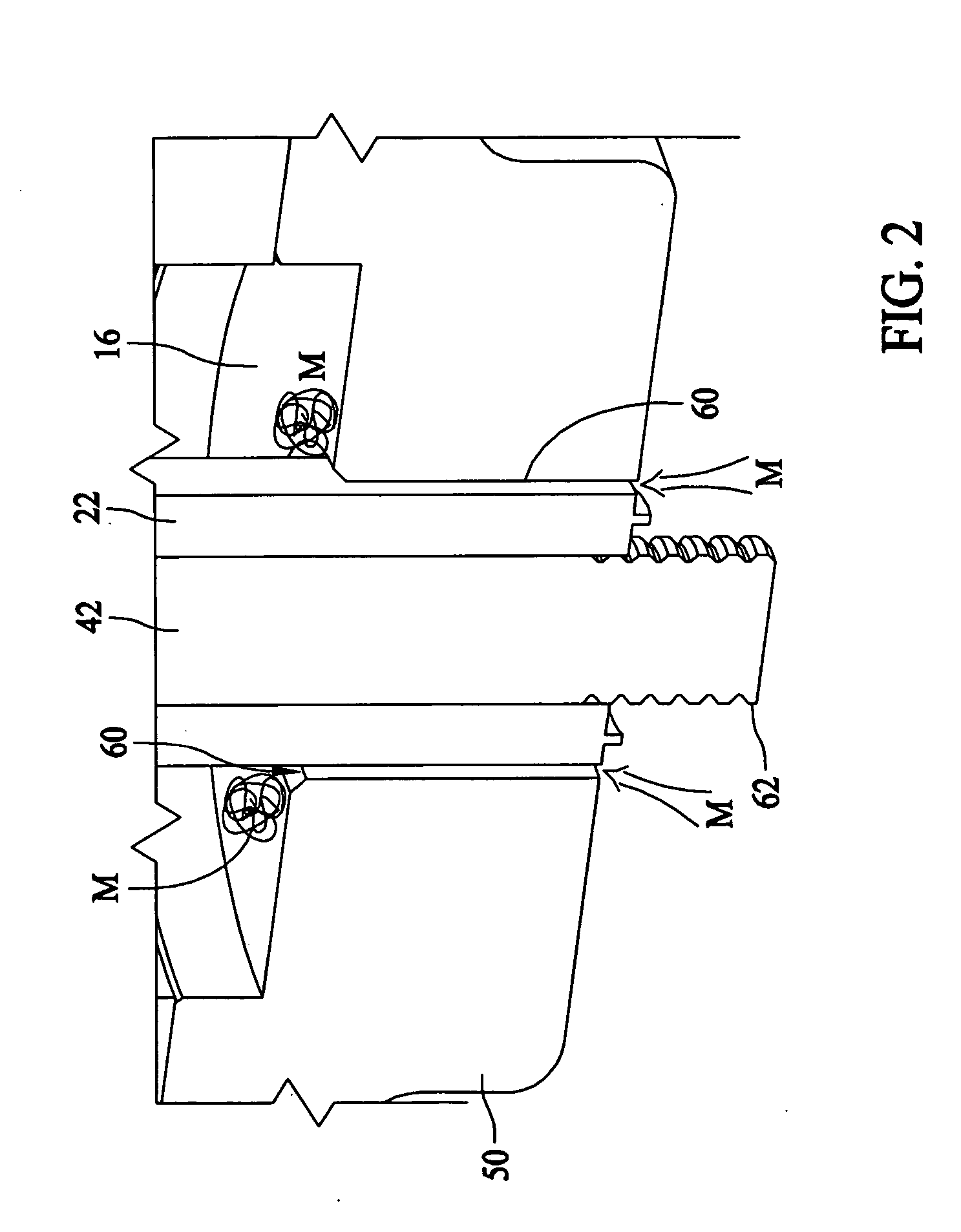
[0021]FIG. 2 is a detailed cross-sectional view of clamping anvil 50, shoulder tool 22, and pin tool 42 of friction stir spot welding device 10, and illustrates migration of plasticized material. In one embodiment, shoulder tool 22 and pin tool 42 rotate counterclockwise when engagin...


PUM

PropertyMeasurementUnit
Diameteraaaaaaaaaa

Abstract

An apparatus for friction stir welding is described that includes a stationary assembly having a bore therethrough, the bore having an inner diameter, and a rotational assembly having a welding end. At least the welding end of the rotational assembly extends through the bore. A portion of the rotational assembly is adjacent the inner diameter of the bore. At least one of the adjacent portion of the rotational assembly and the inner diameter of the stationary assembly are configured such that rotation of the rotational assembly will cause plasticized material from a welding process that has entered an area between the adjacent portion and the inner diameter to move towards a welding zone located proximate the welding end.

Description

BACKGROUND OF THE INVENTION [0001] This invention relates generally to welding processes and more specifically, to methods and systems to facilitate flash reduction and weld integrity in friction stir welding processes. [0002] Friction stir welding is typically utilized for joining together work pieces of materials such as metals and plastics. A friction stir welding tool has a shoulder at its distal end and a non-consumable rotatable welding pin extending downward centrally from the shoulder. Some known friction stir welding tools include a shoulder fixed in position with respect to the pin and other known friction stir welding tools include a pin that is movable with respect to the shoulder. [0003] In a typical friction stir weld operation, two work pieces are supported on a backing plate and are positioned so that the work piece edges where the weld is to be formed are held in direct contact to form an interface. The tool is then positioned so that the rotating pin is in contact ...

Claims


Application Information

Patent Timeline
IPC IPC(8): B23K20/12B23K37/00B23K31/02
CPCB23K20/1255Y10T29/49826B23K20/1265B23K20/126
Inventor BURTON, KURT A.MATLACK, MICHAEL P.
Owner THE BOEING CO
Why Eureka
Try Eureka