

Electrostatic ultrasonic transducer, ultrasonic speaker, sound signal reproducing method, ultra directional acoustic system and display device
- Summary
- Abstract
- Description
- Claims
- Application Information
AI Technical Summary
Benefits of technology
Problems solved by technology
Method used
Image

Examples
first embodiment
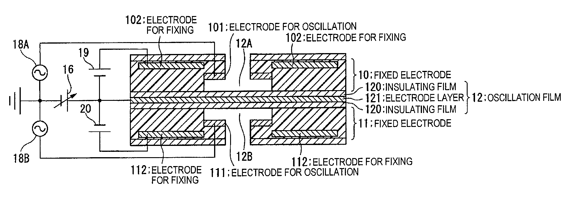
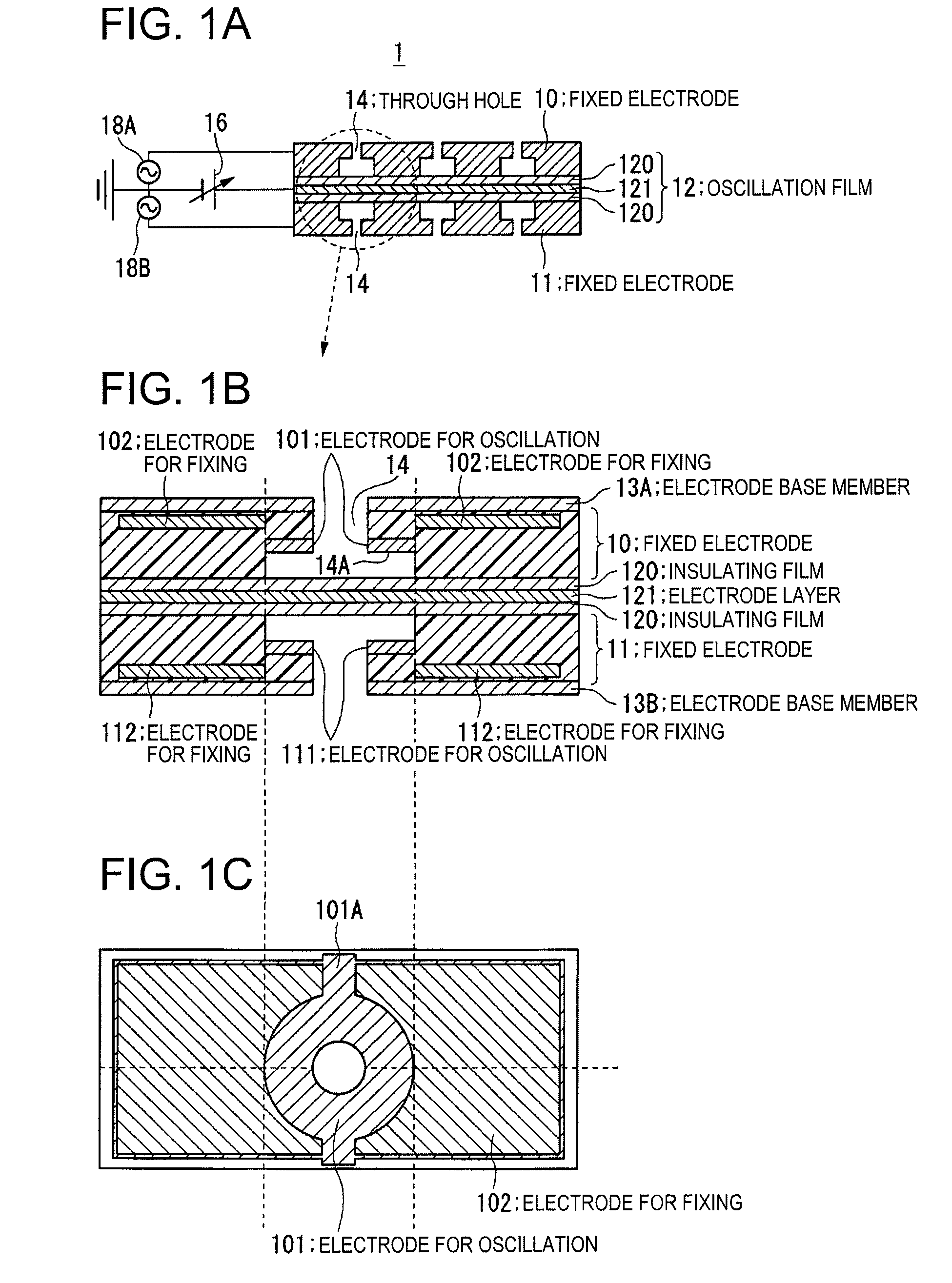
[0066]FIGS. 1A, 1B and 1C show an ultrasonic transducer in accordance with a first embodiment of the invention. An example shown in FIGS. 1A, 1B and 1C is an example of applying the invention to a push-pull type electrostatic ultrasonic transducer. FIG. 1A shows a whole structure of a push-pull type electrostatic ultrasonic transducer. The electrostatic ultrasonic transducer 1 shown in FIG. 1A has a structure basically same as that of the electrostatic ultrasonic transducer shown in FIGS. 8A and 8B, which is described above. In the ultrasonic transducer shown in FIGS. 1A, 1B and 1C, however, plural electrode patterns are formed in the fixed electrodes 10 and 11 and the fixed electrodes 10 and 11 are formed from an insulating material for the purpose of forming plural electrode patterns.
[0067]FIG. 1B is a partially enlarged view of FIG. 1A. FIG. 1B shows an example of arrangement of the electrodes for oscillation and the electrodes for fixing as the plural electrode patterns. FIG. 1...
second embodiment
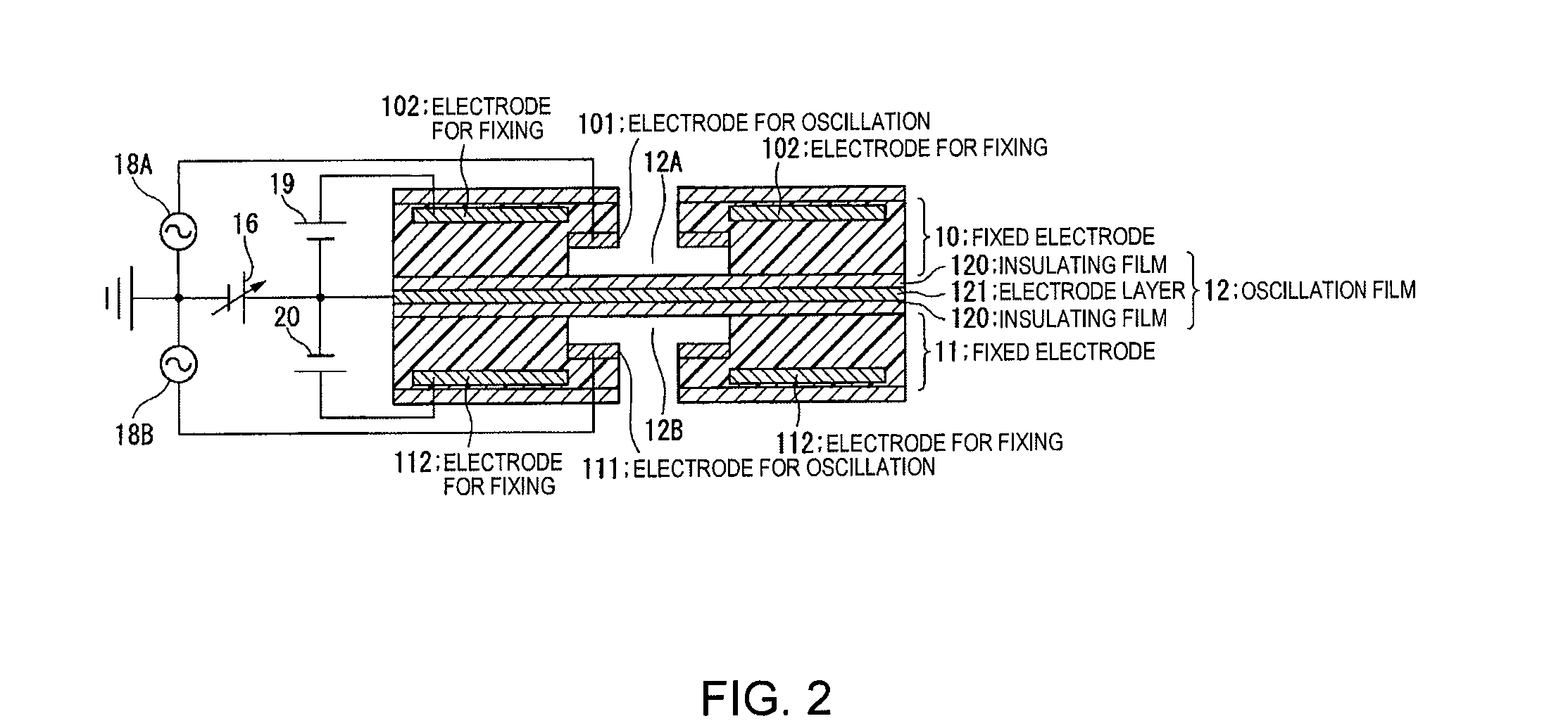
[0079]FIGS. 3A and 3B show an electrostatic ultrasonic transducer in accordance with a second embodiment of the invention. An example shown in FIGS. 3A and 3B is an example of arrangement of the electrodes for fixing 102 and 112, which are provided more closely to the oscillation film 12 than the case of the first embodiment shown in FIGS. 1A to 1C. Such arrangement allows the direct current voltage necessary to fix the electrodes for fixing 102 and 112 and the oscillation film 12 by means of electrostatic force to be made small.
third embodiment
[0080] The electrostatic ultrasonic transducer in accordance with the embodiments of the invention can be achieved not only by a push-pull type electrostatic ultrasonic transducer but also by a pull type electrostatic ultrasonic transducer.
[0081]FIGS. 4A, 4B, 4C and 4D show an electrostatic ultrasonic transducer in accordance with a third embodiment of the invention. FIGS. 4A, 4B, 4C and 4D show an example of forming a pull type electrostatic ultrasonic transducer.
[0082]FIG. 4A shows a whole structure of an electrostatic ultrasonic transducer 2. FIG. 4B is a partially enlarged view of FIG. 4A and shows an example of arrangement of an electrode for oscillation and an electrode for fixing. FIG. 4C shows an example of signal connection. FIG. 4D shows a modification of the fixed electrode 11.
[0083] An example shown in FIGS. 4A, 4B, 4C and 4D is an example of a structure in which the upper fixed electrode 10 of the electrostatic ultrasonic transducer 1 shown in FIGS. 1A to 1C is remov...
PUM
 Abstract
Description
Claims
Application Information