Piezoelectric acoustic element, acoustic device, and portable terminal device

Inactive Publication Date: 2007-08-02
NEC CORP
View PDF6 Cites 18 Cited by
  • Summary
  • Abstract
  • Description
  • Claims
  • Application Information

AI Technical Summary

Benefits of technology

[0019] In the piezoelectric acoustic element of the present invention, because the piezoelectric element, as the vibration source, and the diaphragm are joined through the elastic vibration transmitting member, the flexion of the piezoelectric element and the elastic reconstruction of the vibration transmitting member act synergistically and the diaphragm vibrates to a large degree. Therefore, even if the flexion of the piezoelectric element is small, the diaphragm will vibrate to a large degree to obtain sufficient sound pressure. Also, even if a diaphragm having a

Problems solved by technology

For example, in the conventional piezoelectric acoustic element, a vibration plate of 20 [mm] in diameter is required to obtain the sound pressure of 90 [dB] when voltage of 1 [V] is applied to the piezoelectric element, and therefore it causes the piezoelectric acoustic element to lose advantages such as compact and lightweight.
(3) since ceramic used as a piezo

Method used


Image

  • Piezoelectric acoustic element, acoustic device, and portable terminal device
  • Piezoelectric acoustic element, acoustic device, and portable terminal device
  • Piezoelectric acoustic element, acoustic device, and portable terminal device

Examples


embodiment 1

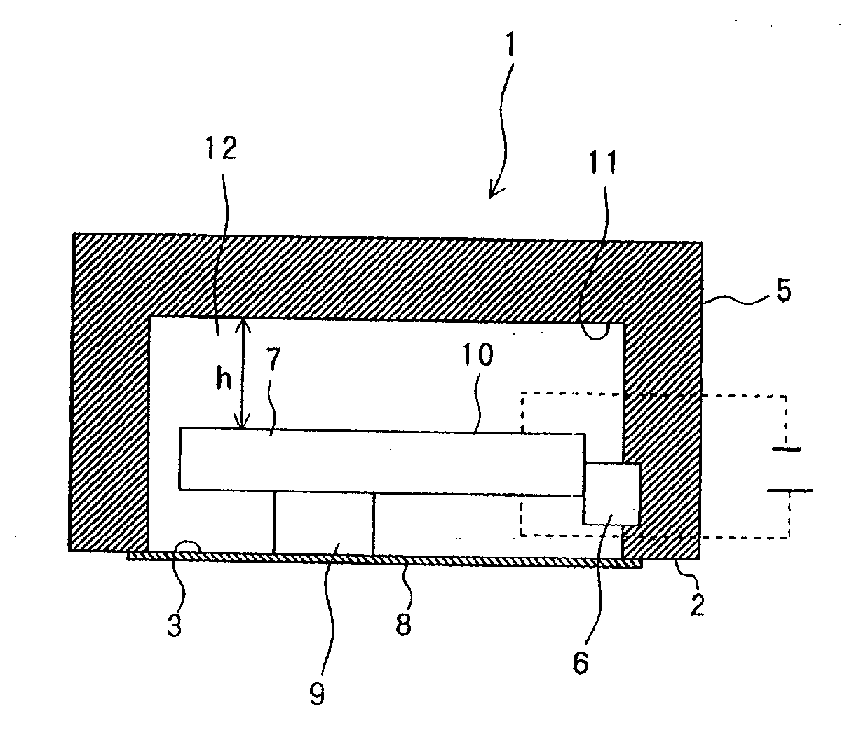
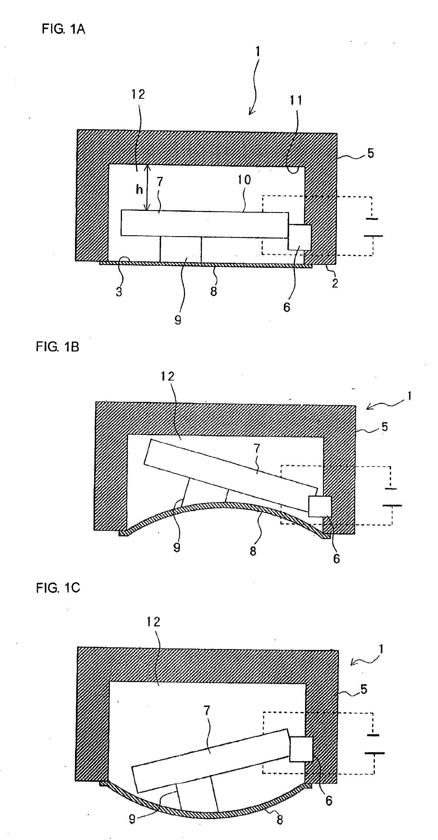
[0086] Hereinafter, explanations are given of embodiments of a piezoelectric acoustic element according to the present invention. FIGS. 1A to 1C are longitudinal sectional views showing schematic arrangements of the piezoelectric acoustic element according to the present embodiment. As shown in FIG. 1A, piezoelectric acoustic element 1 according to the present embodiment has hollow casing 5 formed with opening 3 in bottom surface 2, piezoelectric element 7 in which one end (fixed end) is fixed to the inner surface of casing 5 through support member 6, and diaphragm 8 extended over opening 3 of casing 5. The other end (free end) of piezoelectric element 7 is joined to diaphragm 8 through vibration transmitting member 9. Both support member 6 and vibration transmitting member 9 are made of elastic materials. Also, space 12, in which (h) is the height, is arranged between upper surface 10 of piezoelectric element 7 and ceiling surface 11 of casing 5.

[0087] Piezoelectric element 7 to w...

embodiment 2

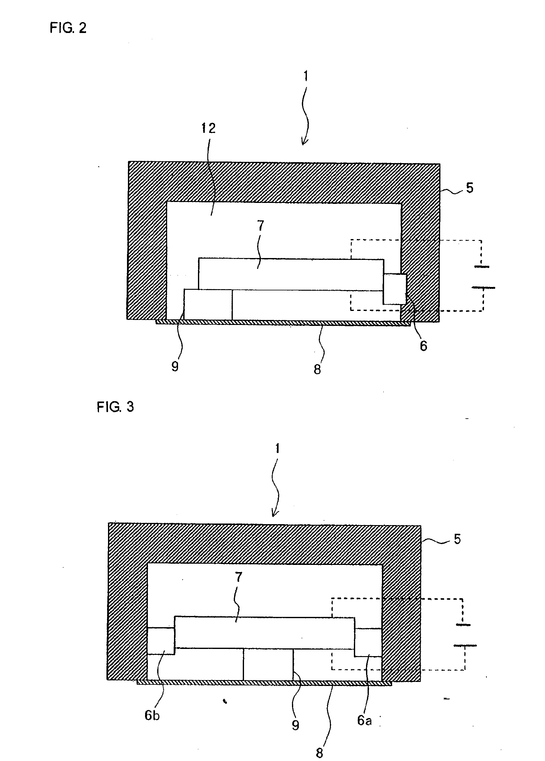
[0090] Next, explanations are given of another embodiment of the piezoelectric acoustic element according to the present invention. FIG. 2 is a longitudinal sectional view showing a schematic arrangement of a piezoelectric acoustic element according to the present embodiment. As shown in FIG. 2, the basic structure of the piezoelectric acoustic element according to the present embodiment is similar to that of Embodiment 1. The present embodiment is different from Embodiment 1 in following two points. One point is that the fixed end of piezoelectric element 7 is fixed to the inner surface of casing 5 through non-elastic support member 6. The other point is that the free end of piezoelectric element 7 is joined to diaphragm 8. Incidentally, in piezoelectric acoustic element 1 shown in FIG. 1, diaphragm 8 is joined to any position between the approximate center in the longitudinal direction and the free end of piezoelectric element 7. In piezoelectric element 7, in which the fixed end ...

embodiment 3

[0092] Next, explanations are given of yet another embodiment of the piezoelectric acoustic element according to the present invention. FIG. 3 is a longitudinal sectional view showing a schematic arrangement of a piezoelectric acoustic element according to the present embodiment. As shown in FIG. 3, the basic structure of the piezoelectric acoustic element according to the present embodiment is similar to that of Embodiment 1. The present embodiment is different from Embodiment 1 in that both ends of piezoelectric element 7 in the longitudinal direction are fixed to the inner surface of casing 5 through support members 6a, 6b. Piezoelectric acoustic element 1 according to the present embodiment has the same structure as the piezoelectric acoustic element of Embodiment 1 and has the same effects. Further, the piezoelectric acoustic element, characterized in that the both ends of piezoelectric element 7 in the longitudinal direction are fixed to the inner surface of casing 5, has an a...


PUM


Abstract

A piezoelectric acoustic element 1 of the present invention comprising a hollow casing 5 having a opening 3, a piezoelectric element 7 that is disposed in said casing 5 and bends when a voltage is applied thereto, and diaphragm 8 provided at the opening 3 of said casing 5; wherein said piezoelectric element 7 and said diaphragm 8 are joined through a vibration transmitting member 9.

Description

TECHNICAL FIELD [0001] The present invention relates to a piezoelectric acoustic element using a piezoelectric element as a vibration source, and an acoustic device and a portable terminal device provided with the piezoelectric acoustic element using the piezoelectric element as the vibration source. BACKGROUND ART [0002] A piezoelectric acoustic element using a piezoelectric element as a vibration source has various advantages, such as being compact, lightweight, power-thrifty, and does not leak magnetic flux, and therefore is expected to be used as an acoustic part of a portable terminal device. In particular, since the mounting volume can be significantly reduced in comparison with the conventional electromagnetic acoustic element, the piezoelectric acoustic element is considered as one critical technique for further reducing size of portable telephones. [0003] However, the sound source of the piezoelectric acoustic element is a vibration plate that bends in accordance with the d...

Claims


Application Information

Patent Timeline
IPC IPC(8): H04R25/00H04R1/28H04R17/00
CPCH04R2499/11H04R17/00
Inventor ONISHI, YASUHARUSASAKI, YASUHIROTOKI, NOZOMI
Owner NEC CORP
Why Eureka
Try Eureka