Efficient control of calendar information in computer graphics

a calendar and computer graphics technology, applied in computing, instruments, electric digital data processing, etc., can solve the problems of occupying too much space, cluttered calendar displays, and laborious use of calendars

Inactive Publication Date: 2007-07-05
SAP AG
View PDF20 Cites 17 Cited by
  • Summary
  • Abstract
  • Description
  • Claims
  • Application Information

AI Technical Summary

Problems solved by technology

However, often, calendar displays can be cluttered and use of the calendars can be laborious. FIG. 1 shows one example of a generic calendar display that illustrates some of the drawbacks in the prior art.
This kind of arrangement occupies too much space and requires too many manual operations to be convenient.

Method used


Image

  • Efficient control of calendar information in computer graphics
  • Efficient control of calendar information in computer graphics
  • Efficient control of calendar information in computer graphics

Examples


Embodiment Construction

[0006] Embodiments of the present invention address the above-described concerns. The embodiments relate to a method and system for providing calendar controls in a compact, uncluttered format. According to the embodiments, multiple calendar control functions are brought together in a streamlined graphical design that conserves space and minimizes the number of manual operations needed

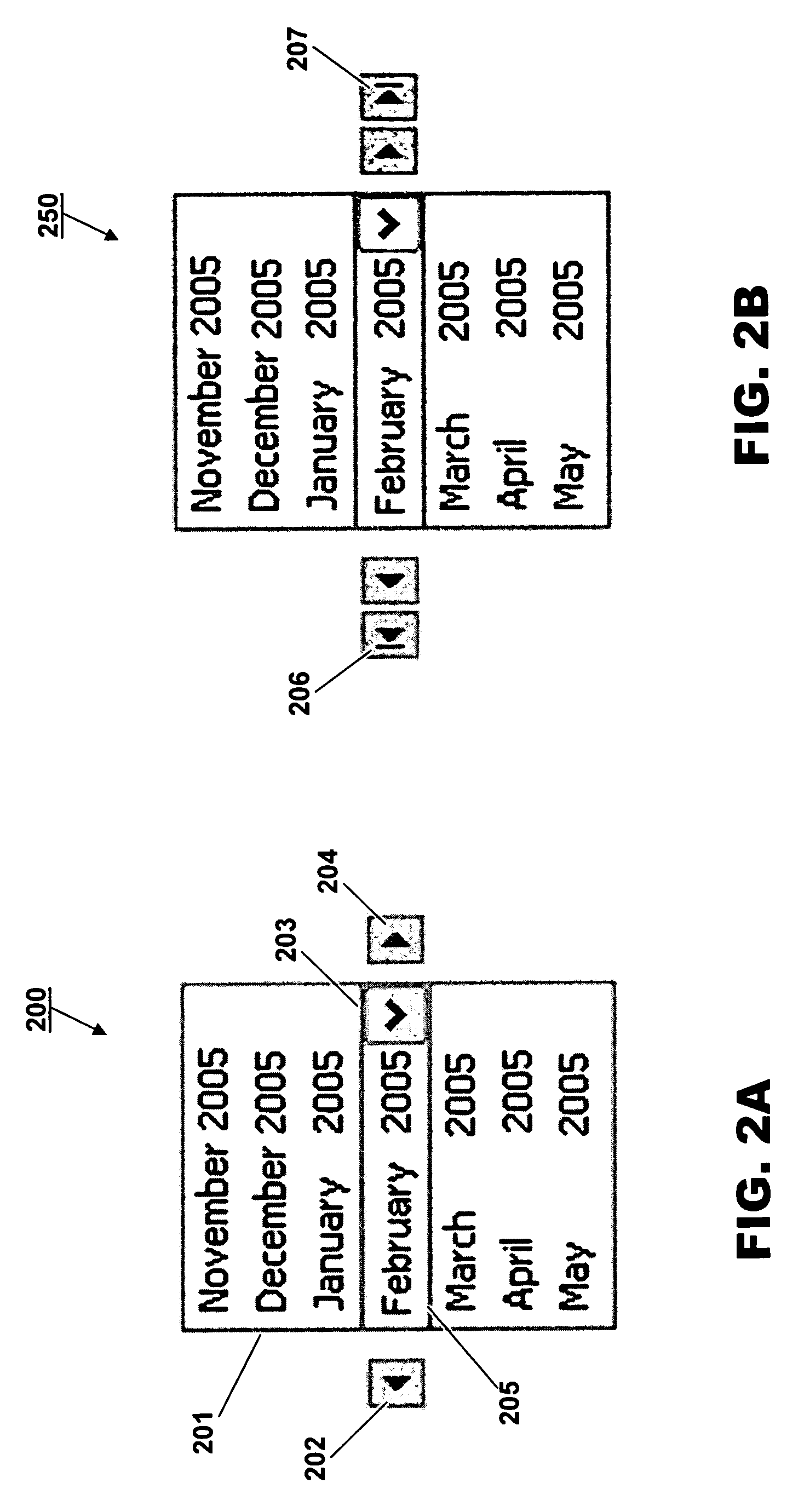
[0007]FIG. 2A shows a computer display 200 for calendar control according to embodiments of the present invention. The display 200 of FIG. 2A includes a compact time range window 201 with associated controls 202, 203 and 204, and an internal shifting or sliding window 205.

[0008] By activating them with an input device (e.g., clicking on them with a mouse), controls 202, 203 and 204 can be used to navigate through calendar information. Control 203 is a scrolling control by which a selection of a month in window 201 may be made. The sliding window 205 tracks the selection made. Left and right sequentia...


PUM


Abstract

Embodiments relate to a method and system for providing calendar controls in computer displays in a compact, uncluttered format. According to the embodiments, multiple calendar control functions are brought together in a streamlined graphical design that conserves space and minimizes the number of manual operations needed

Description

BACKGROUND OF THE INVENTION [0001] Calendars appear in many computer applications. However, often, calendar displays can be cluttered and use of the calendars can be laborious. FIG. 1 shows one example of a generic calendar display that illustrates some of the drawbacks in the prior art. The calendar display 100 has separate controls 101, 102 and 103 for defining / displaying a time span, a month and a year, respectively. This kind of arrangement occupies too much space and requires too many manual operations to be convenient. Improvement is called for.BRIEF DESCRIPTION OF THE DRAWINGS [0002]FIG. 1 shows an example of a prior art calendar control graphic; [0003]FIGS. 2A, 2B, 3 and 4 show examples of calendar control graphics according to embodiments of the present invention; [0004]FIG. 5 shows a system according to embodiments of the present invention; and [0005]FIGS. 6 and 7 show processes according to embodiments of the present invention. DETAILED DESCRIPTION [0006] Embodiments of t...

Claims


Application Information

Patent Timeline
Patent Type & Authority Applications(United States)
IPC IPC(8): G06F3/00
CPCG06Q10/109
Inventor HAUG, TOBIAS
Owner SAP AG
Why Eureka
Try Eureka