

Wearable bottle opening device
a bottle opener and wearable technology, applied in the direction of buckles, liquid handling, instruments, etc., can solve the problems of difficulty in removal and inability to use bottle openers
- Summary
- Abstract
- Description
- Claims
- Application Information
AI Technical Summary
Benefits of technology
Problems solved by technology
Method used
Image

Examples
specific examples
Example 1
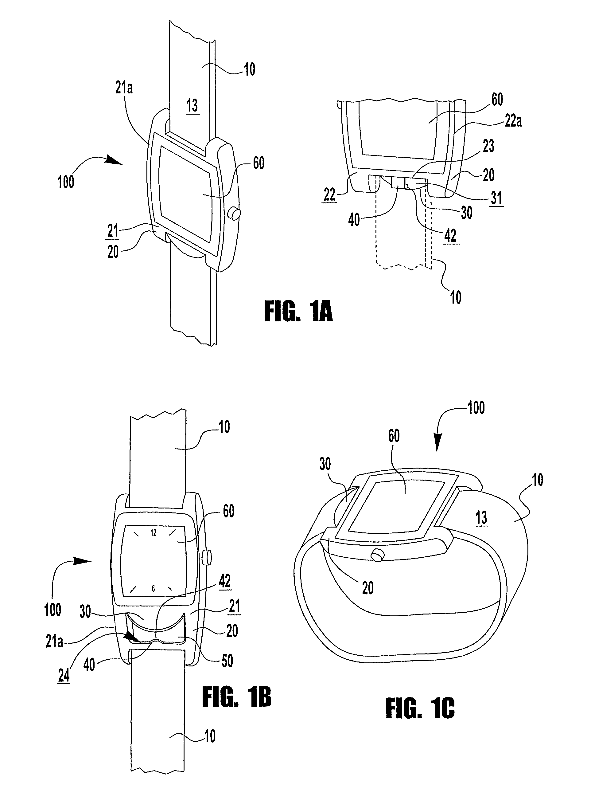
[0040]FIGS. 1A and 1C show an isometric views of an example in which the wearable accessory item is a wrist watch that comprises a band that wraps around a wearer's wrist, a mounting plate 20 attached thereto, a pry plate 30, a pry bar 40, and a decorative piece 60 that is a watch face. Mounting plate 20 is attached to strap 10 by attachment means (not shown in FIG. 1A, 1C). Mounting plate 20 is solid and has first 21, second 22, and third 23 surfaces. Edges 21a, 22a of first and second surfaces 21, 22 are slightly curved. Pry plate 30 is substantially semi-circular in shape and pry bar 40 is substantially square in shape. Pry plate 30 and pry bar 40 are unitary with mounting plate 20. Pry plate 30 and pry bar 40 project from third surface 23 of mounting plate 20 with first 31 and second 42 engaging surfaces, respectively, being substantially opposed. Pry plate 30 is positioned in first plane 1 and pry bar 40 is positioned in third plane 3. As shown, pry bar 40 has a lip 4...
example 2
[0041]FIG. 1B shows an isometric view of an example in which the wearable accessory item 100 is a wrist watch that comprises a band 10 that extends around a wearer's wrist, a mounting plate 20 attached thereto, a pry plate 30, a pry bar 40, and a decorative piece 60 that is a watch face. Mounting plate 20 has first 21, second 22, third 23, and fourth 24 surfaces. Third and fourth surfaces 23, 24 are substantially opposed and define opening 50 into which bottle cap 210 fits during use. Edges 21a, 22a of first and second surfaces 21, 22 are slightly curved. Pry plate 30 is substantially semicircular in shape and pry bar 40 is substantially square in shape. Pry plate 30 and pry bar 40 are unitary with mounting plate 20. Pry plate 30 and pry bar 40 project from third and fourth surfaces 23, 24 of mounting plate 20, respectively. Pry plate 30 is positioned in first plane 1 and pry bar 40 is positioned in third plane 3. Third plane 3 is oriented to first plane 1 at an angle of about 45°. ...
example 3
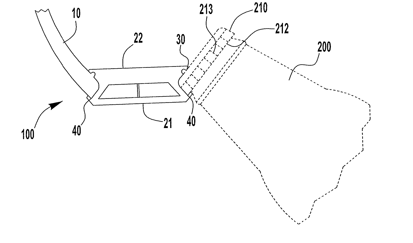
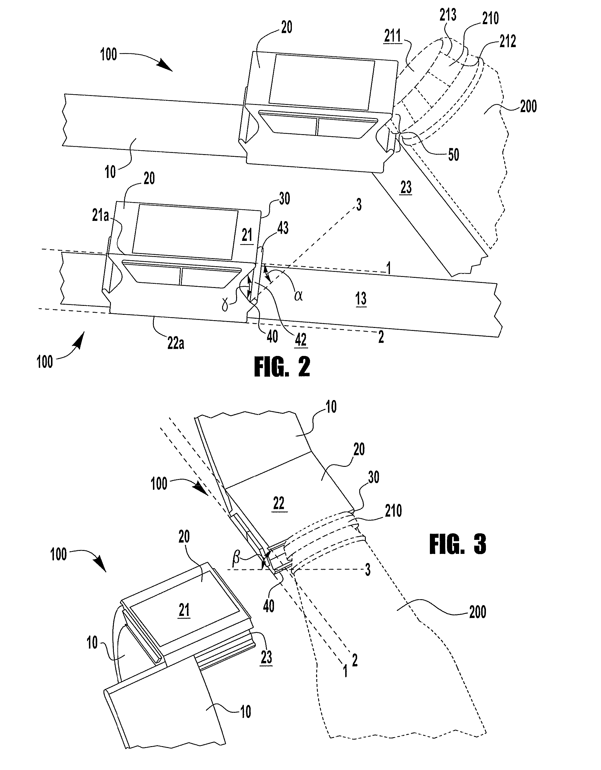
[0042]FIG. 2 shows isometric views of another example of the wearable accessory item 100. Accessory item 100 comprises a strap 10, a mounting plate 20 having first, second, and third surfaces 21, 22, 23, and a pry plate 30 and pry bar 40 unitarily formed with mounting plate 20. Second surface 22 of mounting plate 20 substantially contacts a surface 13 of strap 10. Strap 10 is a single piece to which mounting plate 20 is attached. Edges 21a, 22a of first and second surfaces 21, 22 is substantially flat. Pry plate 30 and pry bar 40 each extend substantially the length of third surface 23 of mounting plate 20 and project from third surface 23 with first and second engaging surfaces 31, 42 being substantially opposed. Pry plate 30 is positioned in first plane 1 and pry bar 40 is positioned in third plane 3, third plane 3 being oriented relative to first plane 1 at an angle α of about 45°. The outermost edge of the engaging surface 42 of pry bar 40 projects further from third surface 23 ...
PUM
 Abstract
Description
Claims
Application Information