Rotatable holder

Inactive Publication Date: 2007-07-19
HEATHROW SCI
View PDF17 Cites 28 Cited by
  • Summary
  • Abstract
  • Description
  • Claims
  • Application Information

AI Technical Summary

Problems solved by technology

This is problematic, since sometimes a user would desire that the

Method used


Image

  • Rotatable holder
  • Rotatable holder
  • Rotatable holder

Examples


Embodiment Construction

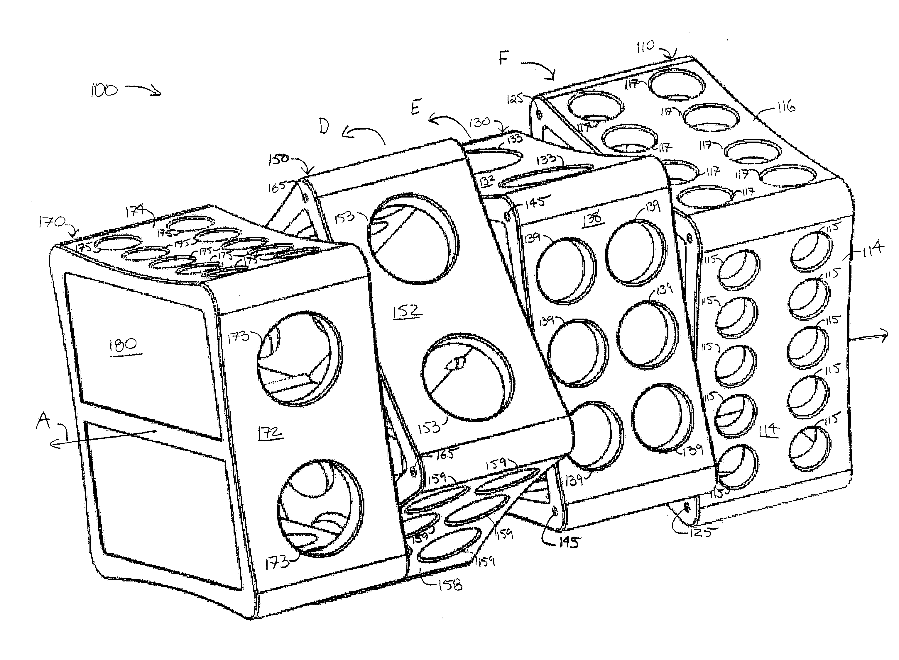
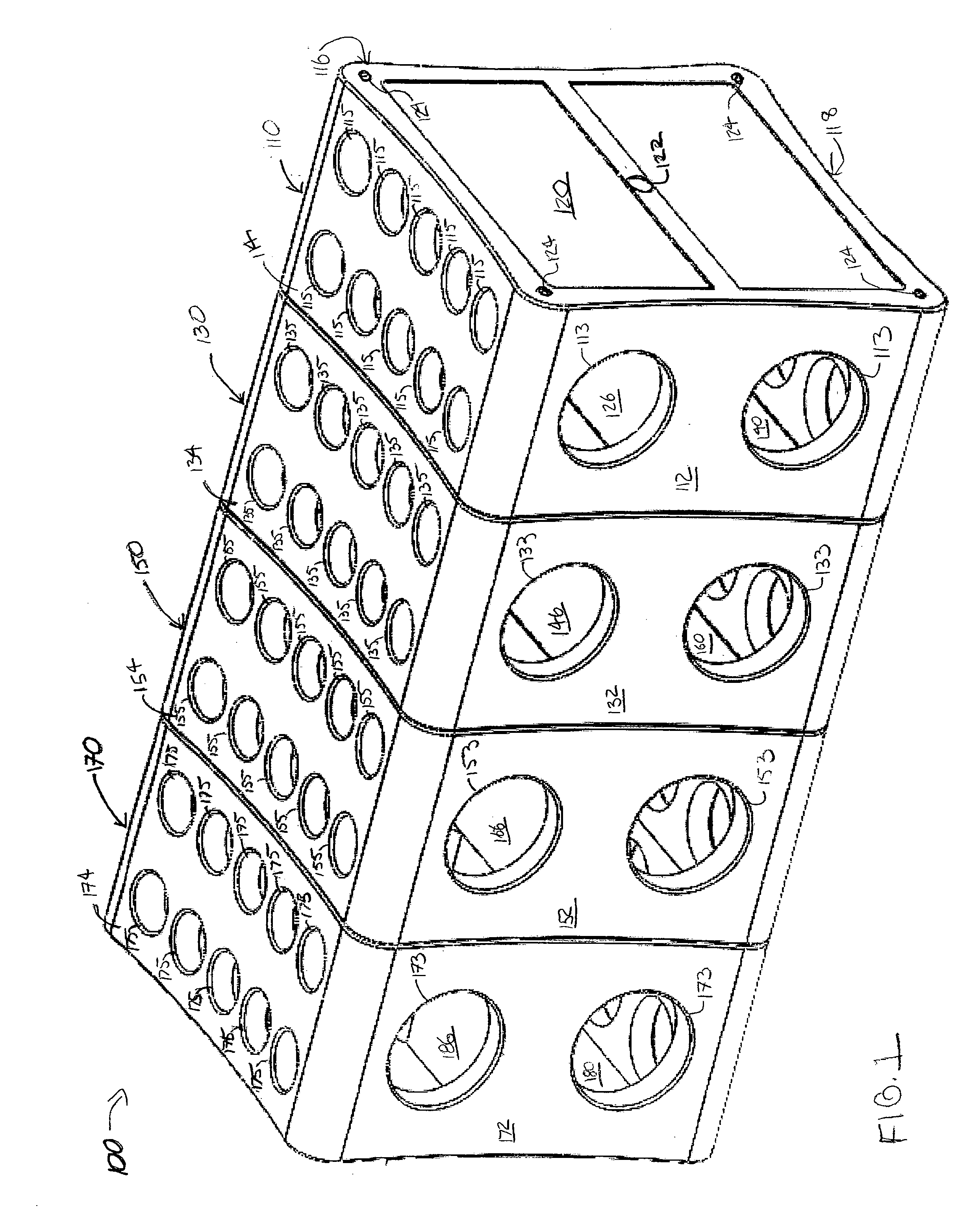
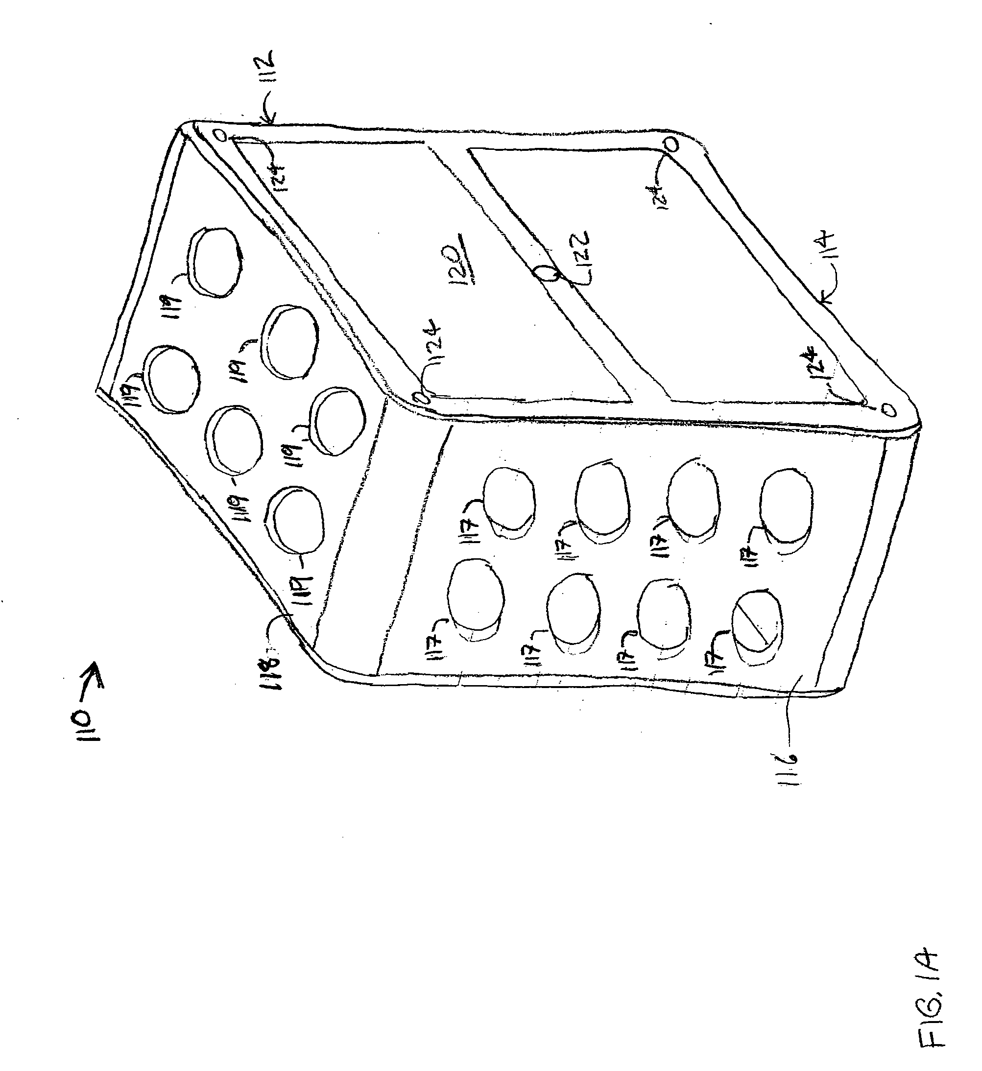
[0013] With reference to the figures, an example of a rotatable holder is described. The holder includes orifices in a variety of sizes that may be used to support one or more objects having a variety of sizes. For example, the orifices may hold pencils, pens and other writing instruments. In addition, the orifices may support vials of different sizes. These vials may include test tubes and other vessels capable of holding liquids. For example, the vials may hold water so that fresh flowers may be supported and displayed. The sections of the holder rotate to provide access to orifices of different sizes, provide the holder with greater stability, and arrange the manner and orientation with which the holder may display and / or hold items.

[0014] In FIGS. 1-4, an example of a rotatable holder 100 is shown. Although the rotatable holder 100 is shown in a horizontal orientation, it may be arranged in a vertical orientation as well. Referring to FIGS. 1 and 1A, the rotatable holder 100 in...


PUM


Abstract

A rotatable holder having first and second sections is provided. The first section has a plurality of first peripheral sides connected to each other and first and second end sides, each end side formed in a plane which is generally perpendicular to the plurality of first peripheral sides. The second section has a plurality of second peripheral sides connected to each other and third and fourth end sides, each end side formed in a plane which is generally perpendicular to the plurality of second peripheral sides. The first and second sections are rotatably coupled with each other along respective end sides of each section. At least one of the peripheral sides forms an orifice for receiving an object.

Description

RELATED APPLICATIONS [0001] The present application claims priority of U.S. Provisional Patent Application No. 60 / 753,882, filed Dec. 23, 2005.BACKGROUND OF THE INVENTION [0002] The present invention relates to a holder, and more specifically to a rotatable holder which includes orifices in a variety of sizes that may be used to support one or more objects having a variety of sizes. [0003] Currently, some holders are sized to hold one type of item, such as writing utensils, test tubes, and other such devices. This is problematic, since sometimes a user would desire that the holder be sized to hold a variety of items having various sizes. Additionally, other times a user would like to hold more items of a first size and fewer items of a second size than the holder is typically configured to hold. SUMMARY OF THE INVENTION [0004] According to one aspect of the present invention, a rotatable holder includes a plurality of sections rotatably coupled with each other along respective end s...

Claims


Application Information

Patent Timeline
IPC IPC(8): A47F7/00
CPCA01G5/04A47F7/0028A47G7/06F16M13/00B01L2200/023B43K23/001B43M99/008B01L9/06F16M11/041F16M11/10
Inventor SMOKOWICZ, NICOLE M.STVARTAK, CHRISTOPHER J.
Owner HEATHROW SCI
Why Eureka
Try Eureka