
Method and apparatus for powder delivery system

a powder delivery system and method technology, applied in the direction of conveyors, liquid handling, packaging goods types, etc., can solve the problems of difficult ergonomic use of methods and apparatuses, rigid drums, and large weight of drums, and achieve the effect of facilitating powder delivery

Inactive Publication Date: 2007-07-26
SWIMC LLC
View PDF30 Cites 12 Cited by
  • Summary
  • Abstract
  • Description
  • Claims
  • Application Information

AI Technical Summary

Benefits of technology

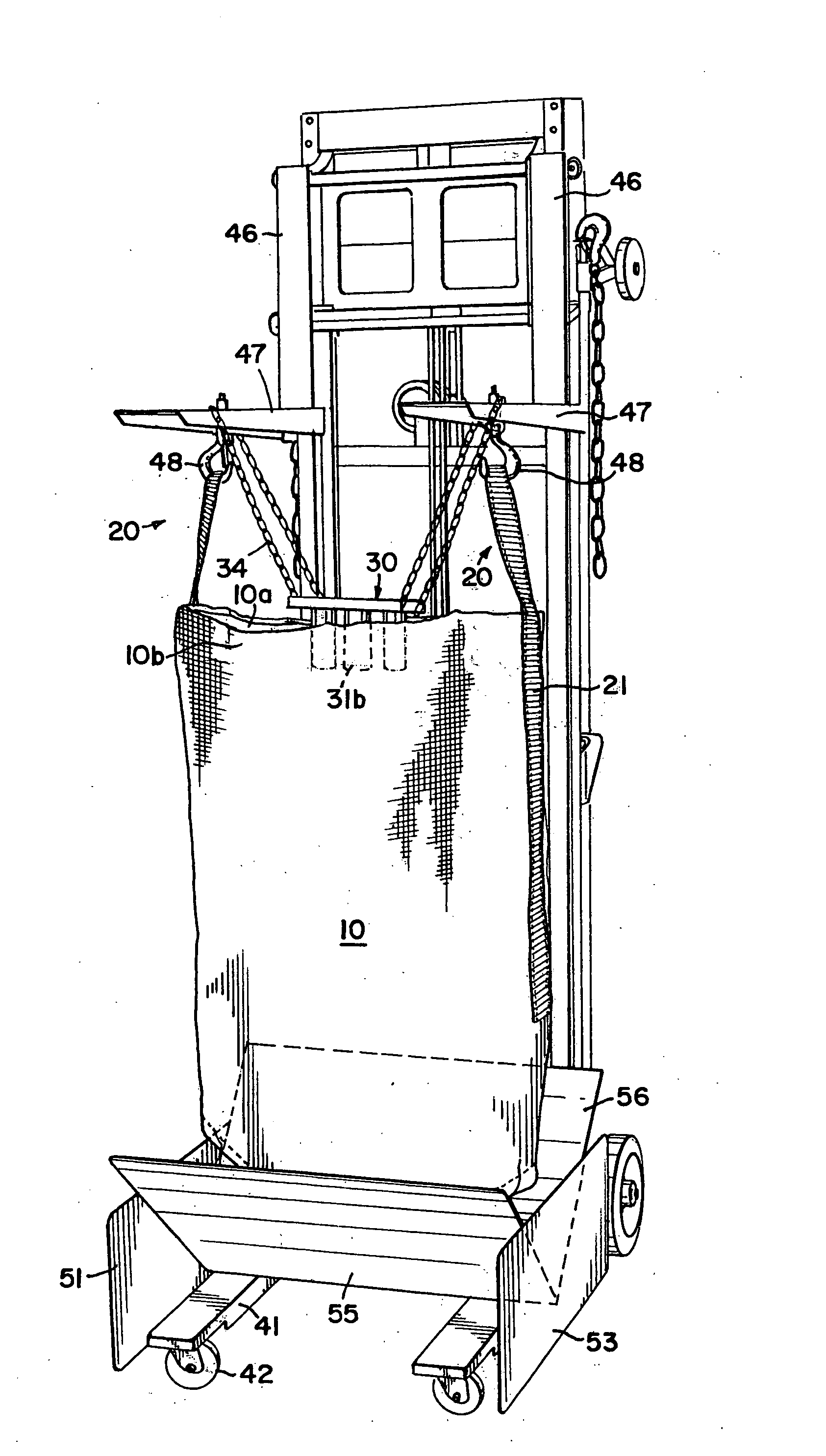
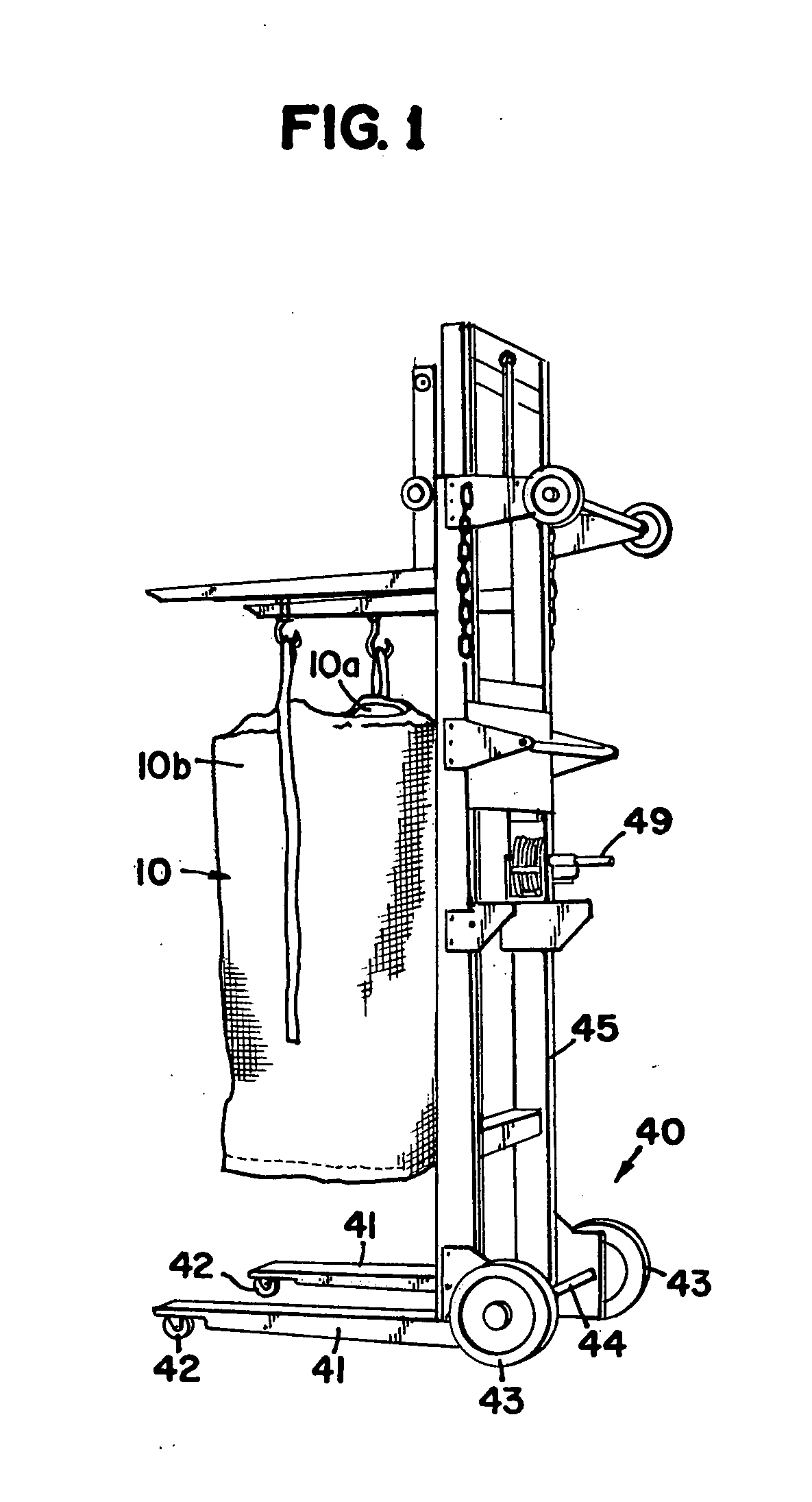
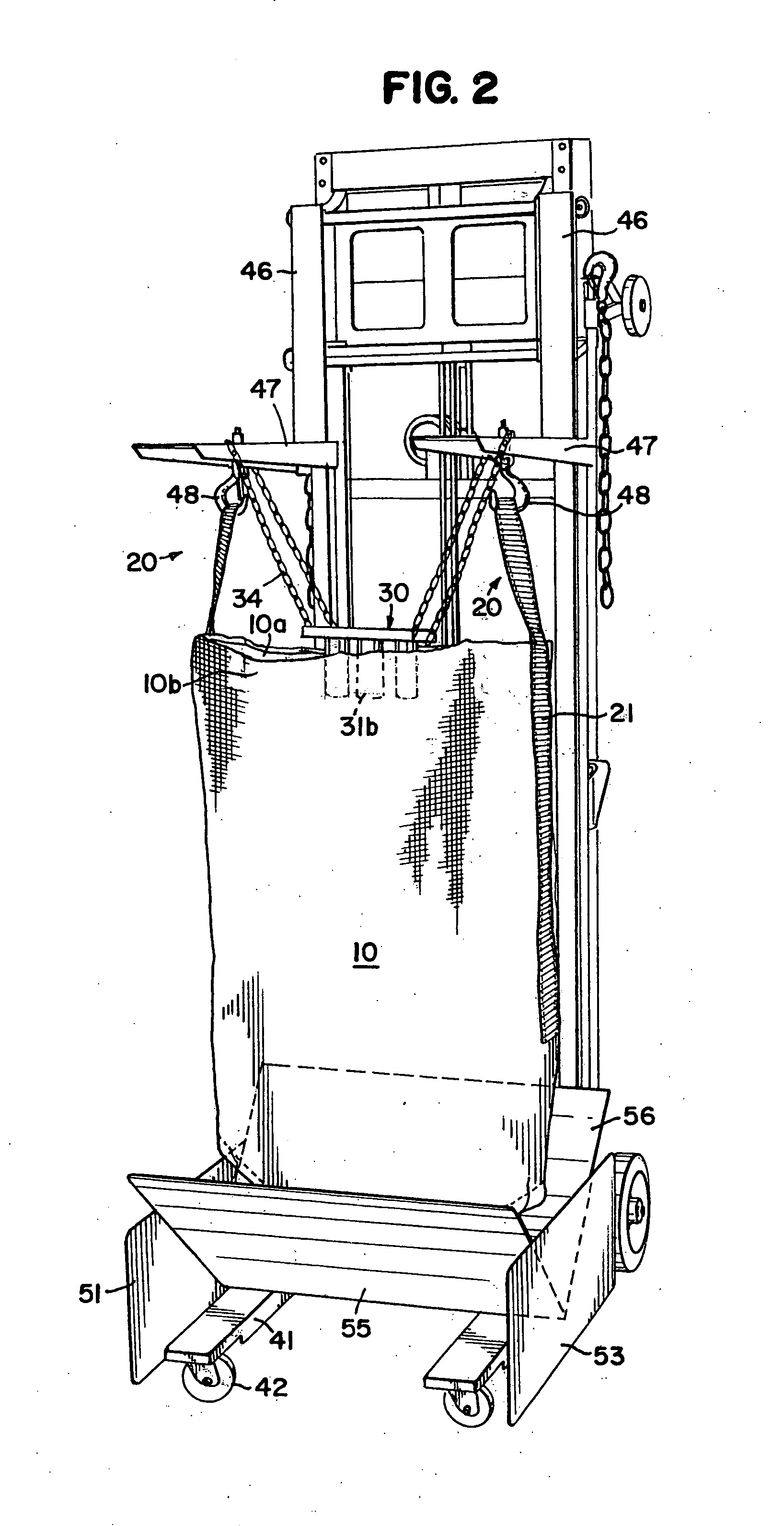
[0007] In one embodiment the invention is an apparatus having at least one feed tube. A flexible bag has a top configured for receiving the at least one feed tube. A support apparatus has at least one support member capable of maintaining the flexible bag in a vertical position. A fixture has a receiving member over which the bag is positioned, wherein the receiving member, when the apparatus is being used to deliver finely divided particulate, positions as least the lower portion of the bag and wherein the apparatus facilitates powder delivery by aspiration through the at least one feed tube.

Problems solved by technology

Such drums are rigid, quite heavy and will typically weigh between 200-300 pounds each when filled.
Such a method and apparatus is difficult to utilize ergonomically.
In addition, the hard sided drums then provide for a problem for waste disposal.

Method used


Image

  • Method and apparatus for powder delivery system
  • Method and apparatus for powder delivery system
  • Method and apparatus for powder delivery system

Examples


first embodiment

[0028] a fixture 50 is shown in FIGS. 2, 3 and 4. The fixture 50 includes a base 51 that includes a first side plate 52 and a second side plate 53. A housing 54 includes a front plate 55 operatively connected to a back plate 56. The bottom portion of the ends of the plates 55 and 56 are operatively connected to the side plates 52 and 53. The housing 54 forms a V shape that is adapted and configured to receive a bag 10. As can be seen, the cross section of the housing 54 decreases when measured along a vertical axis toward the ground. An air driven vibratory motor 57 is operatively connected to the housing 54. The operation of such a motor 57 is well known in the art. The motor 57 vibrates the housing, and thereby the powder inside of the bag 10 to aid in the dispensing of the powder. FIG. 4 shows a bag 10 that has been positioned in the fixture 50. As can be seen, the lower portion of the bag deforms and generally conforms to the shape of the housing 54.

[0029] Another embodiment is ...

third embodiment

[0030] A third embodiment shows a fixture 70 in FIGS. 9 and 10. The fixture 70 is generally conical and has a base 71. The base 71 is generally rectangular and has an opening that is sized and configured to receive the conical shape formed by the housing 74. The housing 74 includes a side plate 75 that is conical and has an opening 74a at the top that is adapted and configured to receive the bag 10 and may also optionally have an opening 74b at the bottom through which the bag 10 may extend. Again, the housing 54 has a decreasingly smaller cross-section when measured along a vertical axis toward the ground and therefore when the bag 10, is positioned in the housing 74, the bag will generally conform to the housing 74 and the bag will likewise have a decreasing cross-section when measured along a vertical axis toward the ground.

[0031] Referring to FIGS. 11 and 12, another embodiment shows a fixture 80. The fixture 80 includes a semi-circular wall 85 operatively connected to a general...


PUM

PropertyMeasurementUnit
Flexibilityaaaaaaaaaa
Shapeaaaaaaaaaa
Levelaaaaaaaaaa

Abstract

A flexible bag (10) has an open top configured and arranged for receiving one or more feed tubes (32). The bag (10) preferably includes at least one attachment member (20) adapted and configured to be secured to a support member (47). A fixture (50), (60), (70), (80) is utilized to receive the bag (10).

Description

[0001] This application claims the benefit of U.S. Provisional Application No. 60 / 757,115, filed Jan. 6, 2006.BACKGROUND OF THE INVENTION [0002] 1. Field of the Invention [0003] This invention is directed toward a method and apparatus for the delivery of powder through a feed line utilizing a flexible bag. [0004] 2. Description of the Prior Art [0005] Powder paint is utilized in electrostatic finishing. The powder is normally received in drum containers such as a 30-gallon drum. Such drums are rigid, quite heavy and will typically weigh between 200-300 pounds each when filled. The powder in the drum must be transferred to a hopper for a spray booth. This is typically done by aspirating the powder that is in the drum to the hopper in the spray booth. Such an apparatus is shown in U.S. Pat. No. 4,505,623. [0006] The drums typically arrive on a pallet. Then, it is necessary that the drums are typically rotated off the pallet, wherein the drums drop 3-4 inches to the floor. The drums ar...

Claims


Application Information

Patent Timeline
IPC IPC(8): B65B1/04
CPCB05B7/1404B05B7/1472B65B69/0091B62B2203/10B62B1/266B62B3/106
Inventor HENDERLEITER, TIMOTHY JAMES SR.
Owner SWIMC LLC
Learn More