
Method and device for controlling an agricultural working machine

a technology for working machines and agricultural machinery, applied in traffic control systems, computation using non-denominational number representations, analog and hybrid computing, etc., can solve problems such as damage to plants, increased costs, and inability to use systems of this type to advance the work

Inactive Publication Date: 2007-08-02
CLAAS SELBSTFAHRENDE ERNTEMASCHINEN GMBH
View PDF7 Cites 11 Cited by
  • Summary
  • Abstract
  • Description
  • Claims
  • Application Information

AI Technical Summary

Benefits of technology

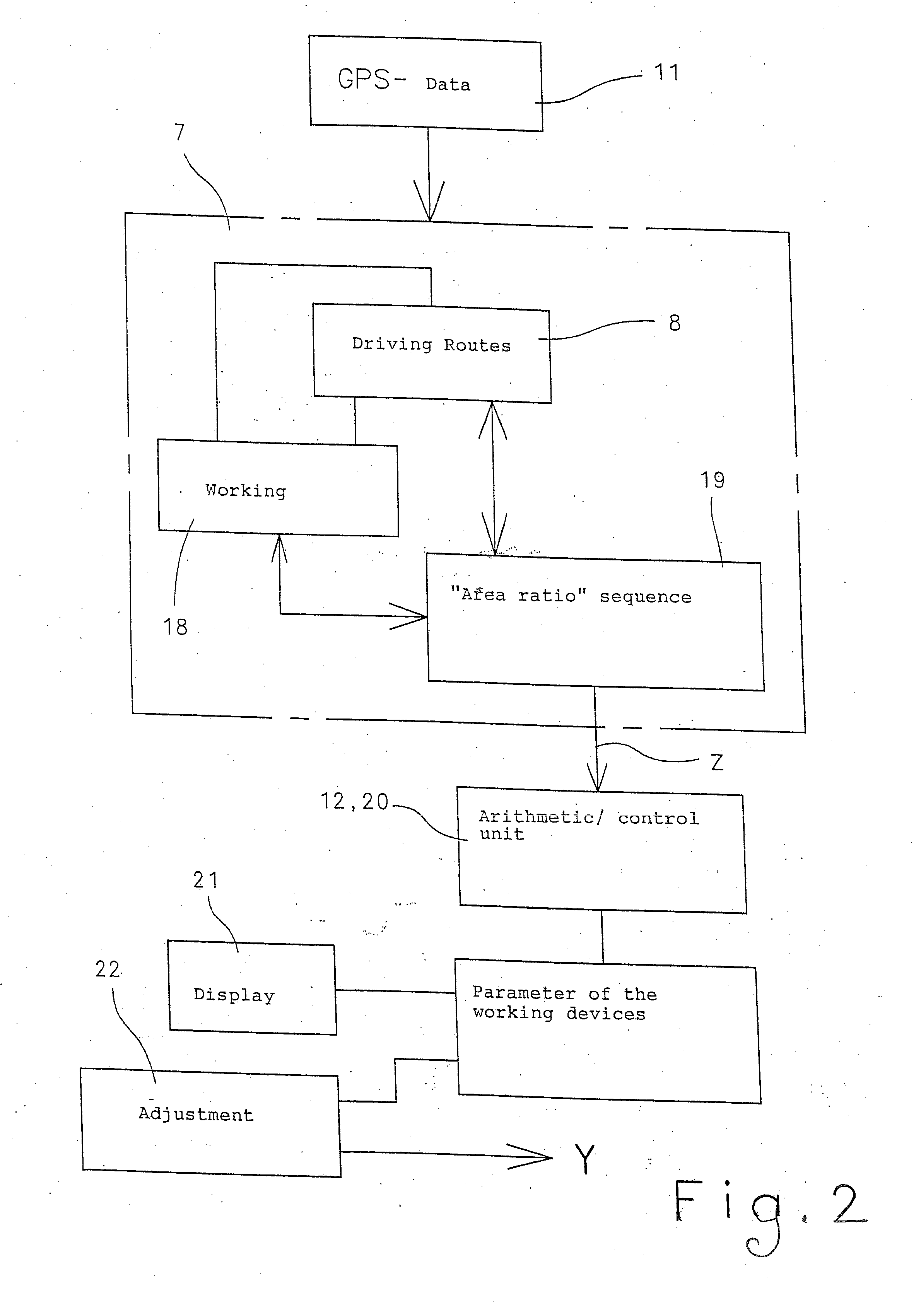
The present invention proposes a route planning system for agricultural working machines that avoids the disadvantages of existing systems. The system adapts parameters of the machine as a function of the shape of the worked or remaining terrain, ensuring efficient use of the machine. The system can adjust parameters of the machine and its attachments, and can also activate predefined working sequences based on the shape of the terrain. The system can also use information about the remaining power requirement to adjust the engine speed and the rotational speed of the various drives and attachments. The system simplifies the operator's job by automatically adapting the determined parameters and displaying them to the operator for influence.

Problems solved by technology

It was not possible to use systems of this type to perform advance planning of driving routes to be worked.
This results in increased costs due to an unnecessarily excessive application of the substance and, in the least favorable case, the multiple applications can also damage the plants.

Method used


Image

  • Method and device for controlling an agricultural working machine
  • Method and device for controlling an agricultural working machine
  • Method and device for controlling an agricultural working machine

Examples


Embodiment Construction

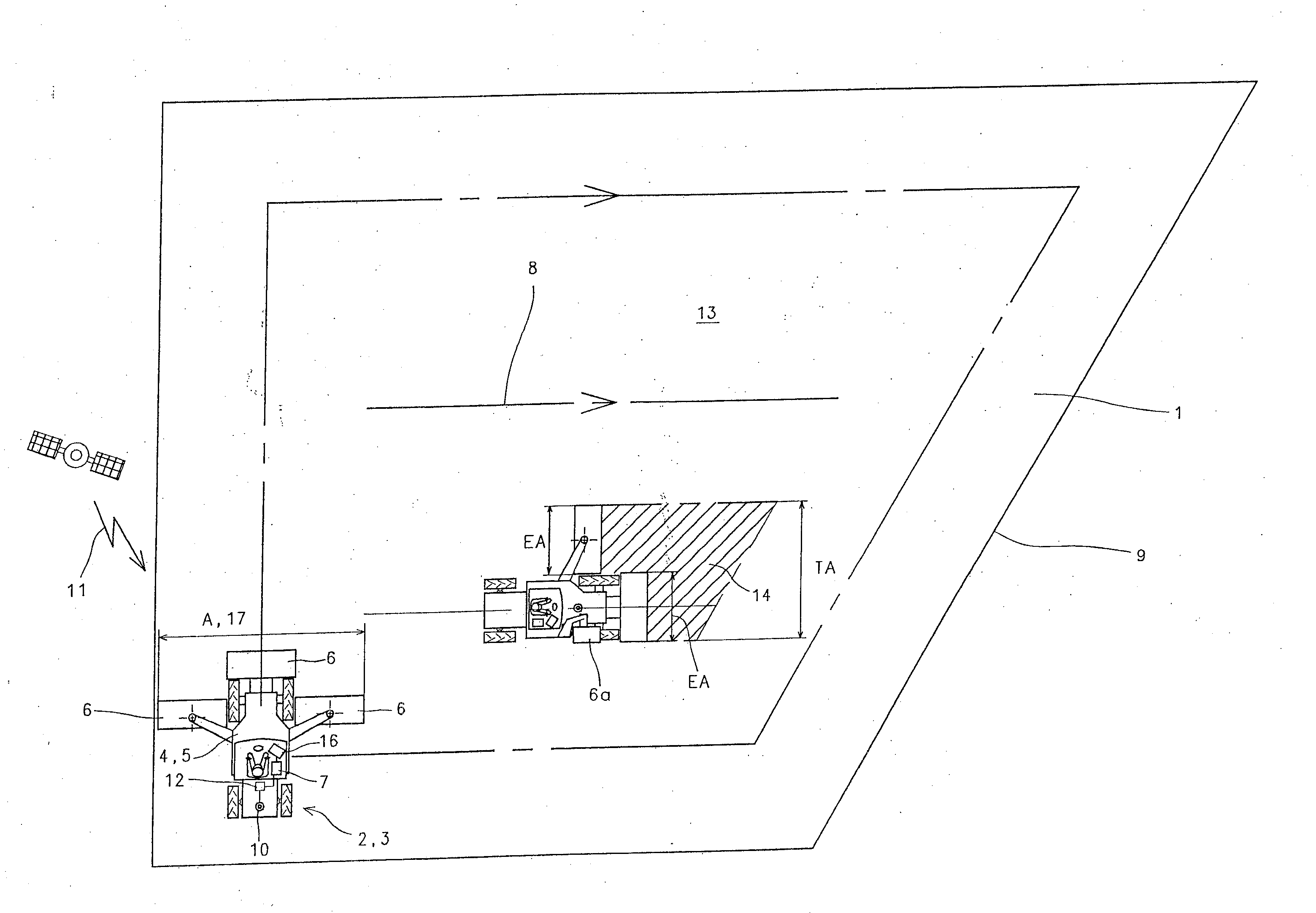
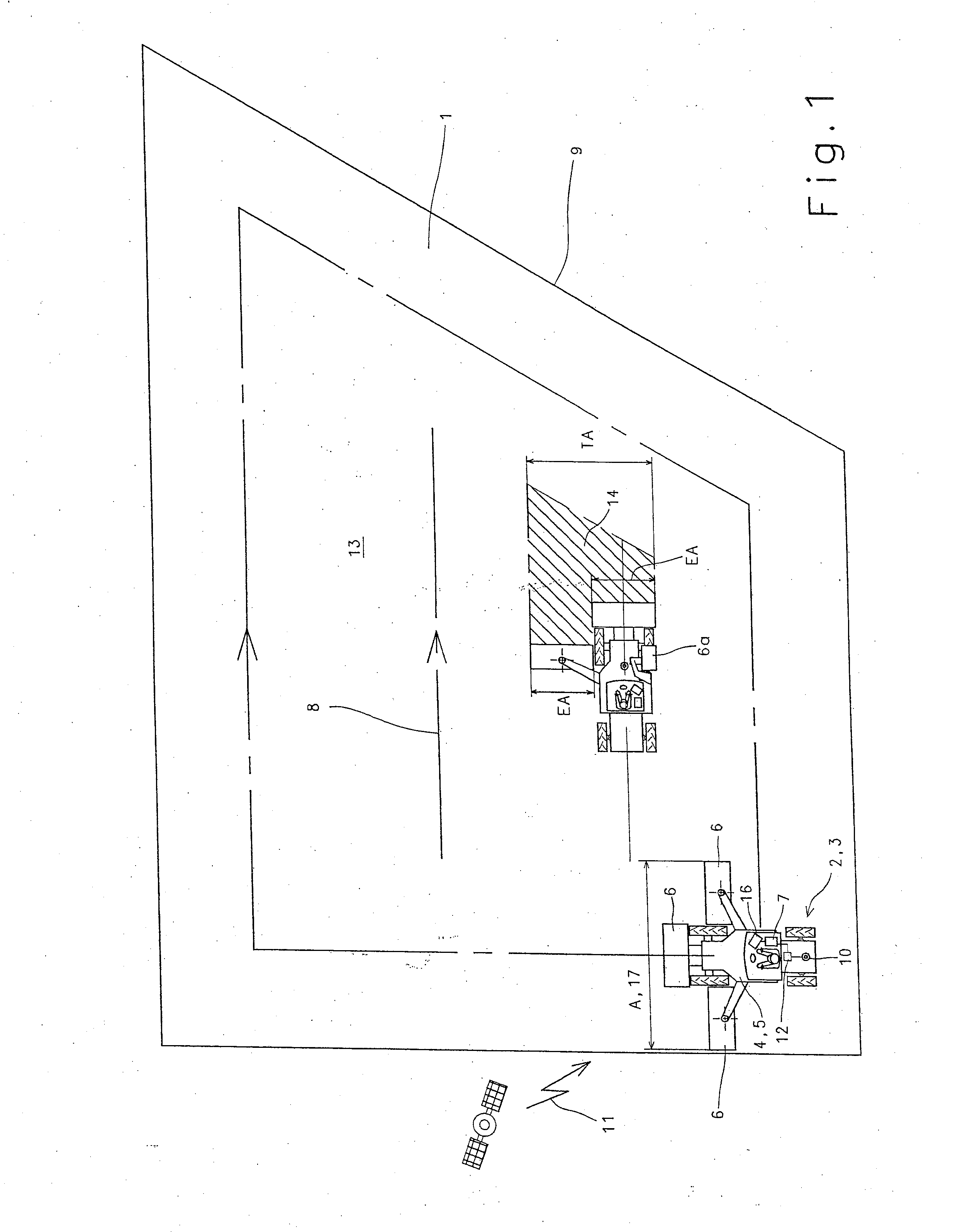
[0018]FIG. 1 shows a schematic illustration of a territory 1 to be worked, said territory being driven over and worked by an agricultural working machine 2 designed as a self-propelled mower mechanism 3. The self-propelled mower mechanism 3 is a carrier vehicle 4 which, in the simplest case, can be designed as a tractor 5, to the front and sides of which working attachments 6 designed as mowing units are assigned. In addition, the agricultural working machine 2 includes a route planning system 7 known per se that is capable of subdividing territory 1 to be worked into “driving routes”8 to be worked by the agricultural working machine 2. These driving routes 8 are usually generated in a first working step by the agricultural working machine 2 first driving around the territory 1 to be worked, following outer contours 9, so that the route planning system 7 can then determine further driving routes 8 as a function of working width A, thereby ultimately ensuring that the territory 1 to ...


PUM


Abstract

A method for controlling an agricultural working machine includes the step of assigning a route planning system (7) to the agricultural working machine (2) for generating driving routes (8) in a territory (1). The route planning system (7) subdivides the territory (1) into a worked territory (13) and a remaining territory area (14), and at least one parameter (17) of the agricultural working machine (2) is adapted as a function of the shape of the worked territory (13) and / or the remaining territory area (14). In this manner it is ensured that the working method of the agricultural working machine (2) or its working attachments (6) is adaptable to the shape of the particular territory (13, 14) to ensure economically efficient use of the agricultural working machine (2). A device for controlling an agricultural working machine also is provided.

Description

BACKGROUND OF THE INVENTION [0001] The present invention relates to a method and a device for controlling an agricultural working machine. EP 0 660 660 discloses equipping agricultural working machines with “GPS” systems to record the position of the agricultural harvesting machine in an area to be worked. In this process, the operator of the machine determined the route to be driven, and the GPS system—that is actively connected to a recording unit—delivered the position data of the vehicle, which were then used in the recording unit to electronically depict the driving path that had been covered. Systems of this type were an initial step in the direction toward recording driving routes, whereby the initial application was only to record driving routes. It was not possible to use systems of this type to perform advance planning of driving routes to be worked. [0002] Building logically on the idea of displaying driving routes, systems as described in EP 0 821 296 enable the generati...

Claims


Application Information

Patent Timeline
Patent Type & Authority Applications(United States)
IPC IPC(8): G01C21/00A01B69/04A01D75/30
CPCA01B69/008A01D41/127
Inventor BRUNNERT, ANDREAS
Owner CLAAS SELBSTFAHRENDE ERNTEMASCHINEN GMBH
Learn More