Concentricity measuring apparatus and method, squareness measuring apparatus and method, and concentricity-squareness measuring apparatus and methdo

a technology of concentricity and measuring equipment, applied in the direction of measuring devices, measuring gauges, instruments, etc., can solve the problems of not being able to simultaneously measure the concentricities of the radial centers of the two holes b>11/b> and b>12, and the radial center of the barrel member b>10

Inactive Publication Date: 2007-08-09
OLYMPUS CORP
View PDF8 Cites 29 Cited by
  • Summary
  • Abstract
  • Description
  • Claims
  • Application Information

AI Technical Summary

Benefits of technology

[0022] According to one aspect of the invention, a method for measuring concentricity of two holes in a cylindrical member, the cylindrical member having the two holes at both ends and a partition wall between the two holes, comprises: supporting the cylindrical member and rotating the cylindrical member about one of the two holes; and measuring the concentricity of a longitudinal center line of the other hole to a longitudinal center line of the one hole, by measuring a relative position of the inner circumferential surface of the other hole to the longitudinal center line of the one hole over the whole inner circumferential surface of the other hole, while the cylindrical member is rotated by the rotation unit.

Problems solved by technology

However, in the above described conventional method for measuring the concentricity by using the measuring microscope or the laser measuring instrument, it is impossible to simultaneously measure the concentricities of the radial centers of the two holes 11 and 12 to the radial center of the barrel member 10.

Method used


Image

  • Concentricity measuring apparatus and method, squareness measuring apparatus and method, and concentricity-squareness measuring apparatus and methdo
  • Concentricity measuring apparatus and method, squareness measuring apparatus and method, and concentricity-squareness measuring apparatus and methdo
  • Concentricity measuring apparatus and method, squareness measuring apparatus and method, and concentricity-squareness measuring apparatus and methdo

Examples


Embodiment Construction

ONE EMBODIMENT

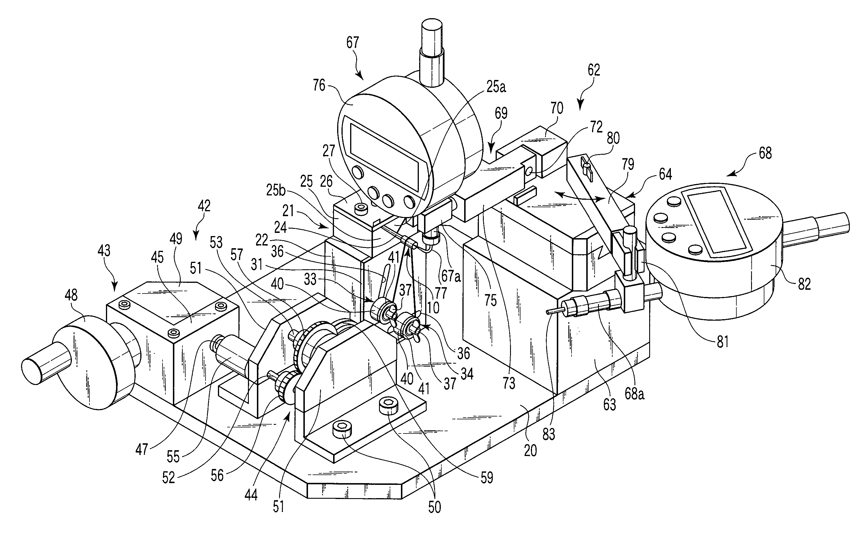
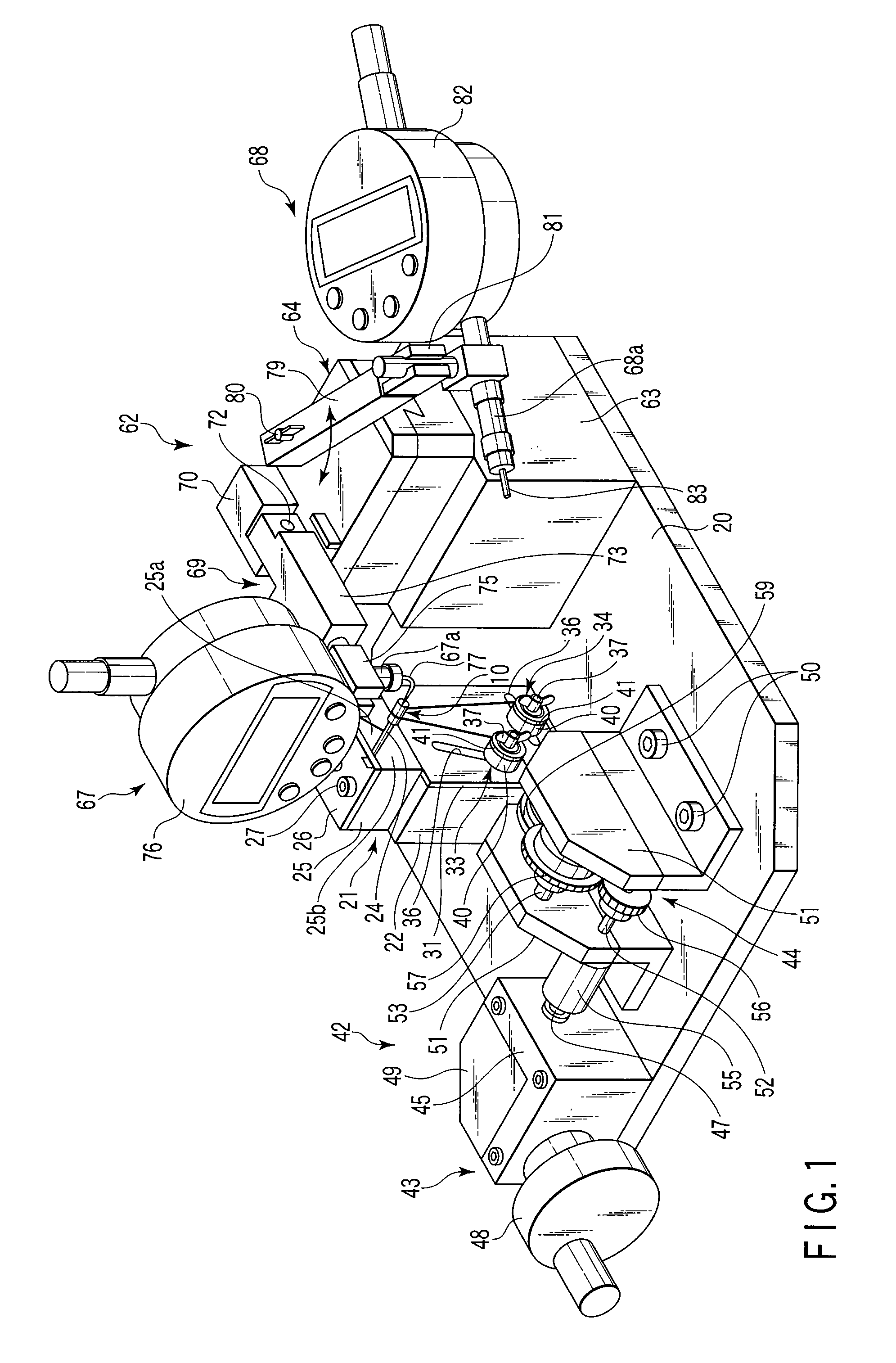
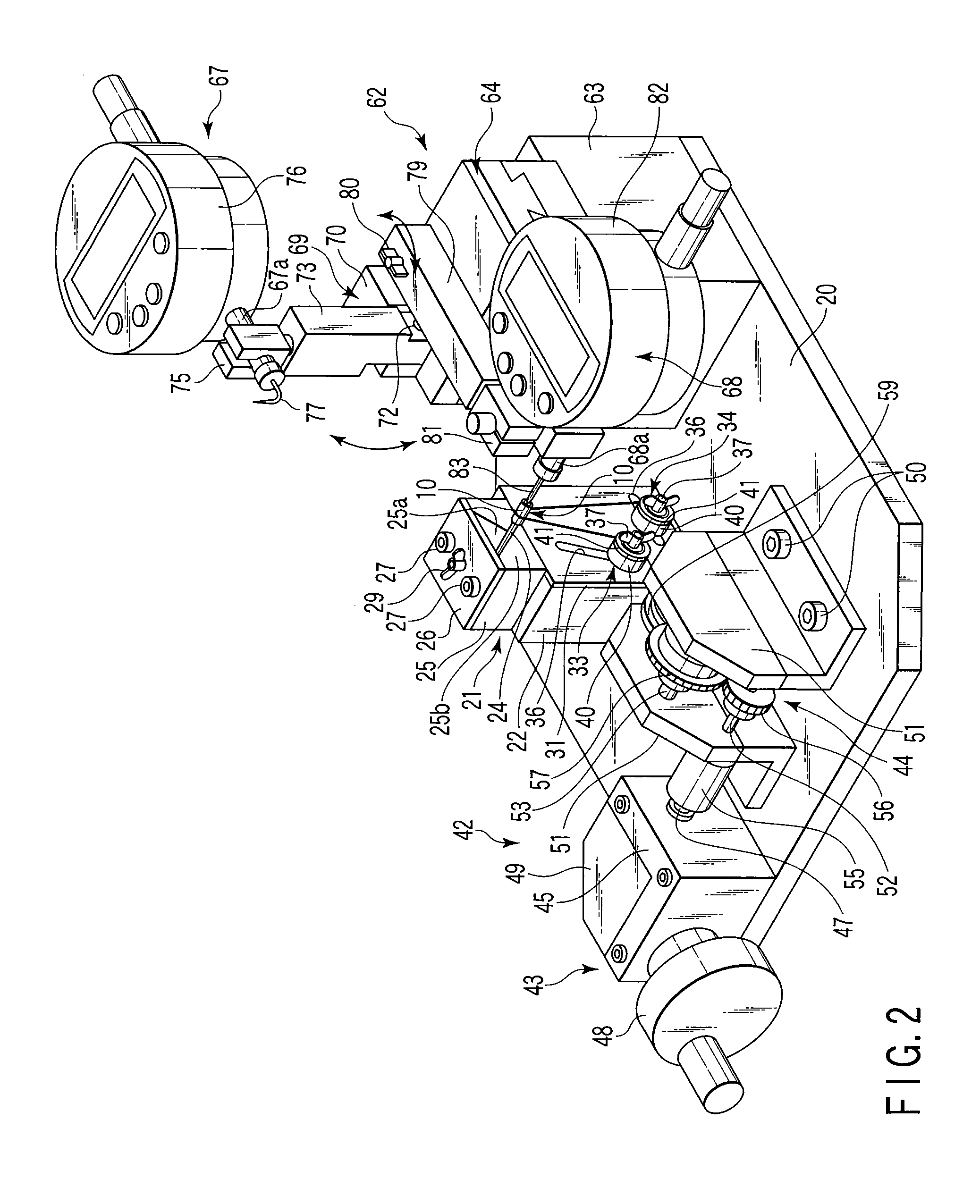
[0043] A concentricity-squareness measuring apparatus according to one embodiment of the invention will be explained with reference to FIG. 1 to FIG. 11.

[0044] The concentricity-squareness measuring apparatus according to the embodiment measures the concentricity of the two holes 11 and 12 formed at the both end surfaces 10a and 10b of the barrel member 10 that is described above with reference to FIGS. 13A and 13B and that is a kind of a conventional cylindrical member. The concentricity-squareness measuring apparatus further measures the squareness of the at least one end surface of the partition wall 13 between the two holes 11 and 12 in the barrel member 10 to the longitudinal center line of at least one of the two holes 11 and 12.

[0045] As shown in FIG. 1 to FIG. 4, a member support mechanism 21 is provided at about the middle of the upper surface of a base plate 20. The member support mechanism 21 includes a support block 22 placed at almost the middle of the u...


PUM


Abstract

An apparatus for measuring concentricity of two holes at both ends of a cylindrical member includes a rotation unit supporting and rotating the cylindrical member about one of the holes, and an unit measuring the concentricity by measuring a relative position of an inner circumferential surface of the other hole to the center line of the one hole over the whole inner circumferential surface, while the member is rotated. An apparatus for measuring squareness of one end surface of a partition wall between the two holes in the cylindrical member to a longitudinal center line of the one hole includes, in addition to the rotation unit, an unit measuring the squareness by measuring a relative position of the one end surface of the partition wall along the longitudinal center line of the other hole over the whole circumference of the one end surface, while the member is rotated.

Description

CROSS-REFERENCE TO RELATED APPLICATIONS [0001] This application is based upon and claims the benefit of priority from prior Japanese Patent Application No. 2006-027598, filed Feb. 3, 2006, the entire contents of which are incorporated herein by reference.BACKGROUND OF THE INVENTION [0002] 1. Field of the Invention [0003] The present invention relates to: an apparatus and method for measuring the concentricity of two holes formed at ends of a cylinder; an apparatus and method for measuring the squareness of at least one end surface of a partition wall between two holes formed at ends of a cylinder to the longitudinal center line of at least one hole; and an apparatus and method for measuring the concentricity of two holes formed at ends of a cylinder and the squareness of at least one end surface of a partition wall between the two holes to the longitudinal center line of at least one hole. [0004] 2. Description of the Related Art [0005] A cylinder provided with two holes at ends is ...

Claims


Application Information

Patent Timeline
Patent Type & Authority Applications(United States)
IPC IPC(8): G01B3/00
CPCG01B5/252
Inventor FURUKAWA, AYUMU
Owner OLYMPUS CORP
Why Eureka
Try Eureka