Eureka AIR delivers breakthrough ideas for toughest innovation challenges, trusted by R&D personnel around the world.

Lift truck

Active Publication Date: 2007-08-09
TYGARD MACHINE & MFG
View PDF7 Cites 7 Cited by
  • Summary
  • Abstract
  • Description
  • Claims
  • Application Information

AI Technical Summary

Benefits of technology

[0005] The present invention provides a mast structure for a lift truck having improved ability to smoothly raise and lower a load, even when the center of gravity of the load is spaced from the centerline plane of the lift truck.
[0007] The present invention additionally provides a lift truck attachment, such as a clamping apparatus, which can easily be mounted on a lift truck.
[0010] According to another form of the present invention, a clamping apparatus for use with a lift truck includes a frame, a plurality of clamping arms mounted on the frame, and a pair of fork engaging members secured to the frame between two of the clamping arms. The clamping apparatus can be easily mounted on a lift truck by inserting forks of the lift truck into the fork engaging members.
[0011] In order to prevent the clamping apparatus from sliding along the forks of the lift truck during use, the lift truck may be equipped with a mounting bracket which is detachably engageable with the clamping apparatus.
[0012] According to yet another form of the present invention, a lift truck includes a truck body and a mast supported by the truck body. The mast includes first uprights disposed parallel to each other, second uprights disposed parallel to each other on opposite widthwise sides of the first uprights, and a guide member supported by one of the uprights for maintaining the first and second uprights parallel to each other. In a preferred embodiment, the guide member comprises a roller mounted on one of the uprights for rolling contact with another of the uprights and having a rotational axis extending in a fore-and-aft direction of the lift truck. The guide member prevents the first uprights from tilting with respect to the second uprights when a moment is applied to the first uprights and thereby allows the first uprights to smoothly translate along the second uprights.
[0013] According to still another form of the present invention, a lift truck attachment for mounting on a lift truck includes first and second fork engaging members each shaped for receiving a horizontal portion of a fork of a lift truck. A latching member is associated with the first fork engaging member and is movable between a first position in which it prevents withdrawal of a fork of a lift truck from the first fork engaging member and a second position in which it permits withdrawal of a fork of a lift truck from the first fork engaging member. In a preferred embodiment, the latching member is disposed to the rear of a vertical portion of a fork of a lift truck when in its first position. The latching member enables the lift truck attachment to be detachably connected to a lift truck so as to prevent the attachment from translating along the forks of the lift truck.

Problems solved by technology

Such a widthwise force or moment can cause the wheels of the carriage to be pressed against the channels or to become misaligned with the channels of the mast, making it difficult for the carriage to travel smoothly up and down the mast.
In addition, because the rollers are typically made of a hard material such as steel, the misalignment can cause the rollers to gouge the channels, resulting in damage to the rollers and / or the channels.

Method used


Image

  • Lift truck
  • Lift truck
  • Lift truck

Examples


Embodiment Construction

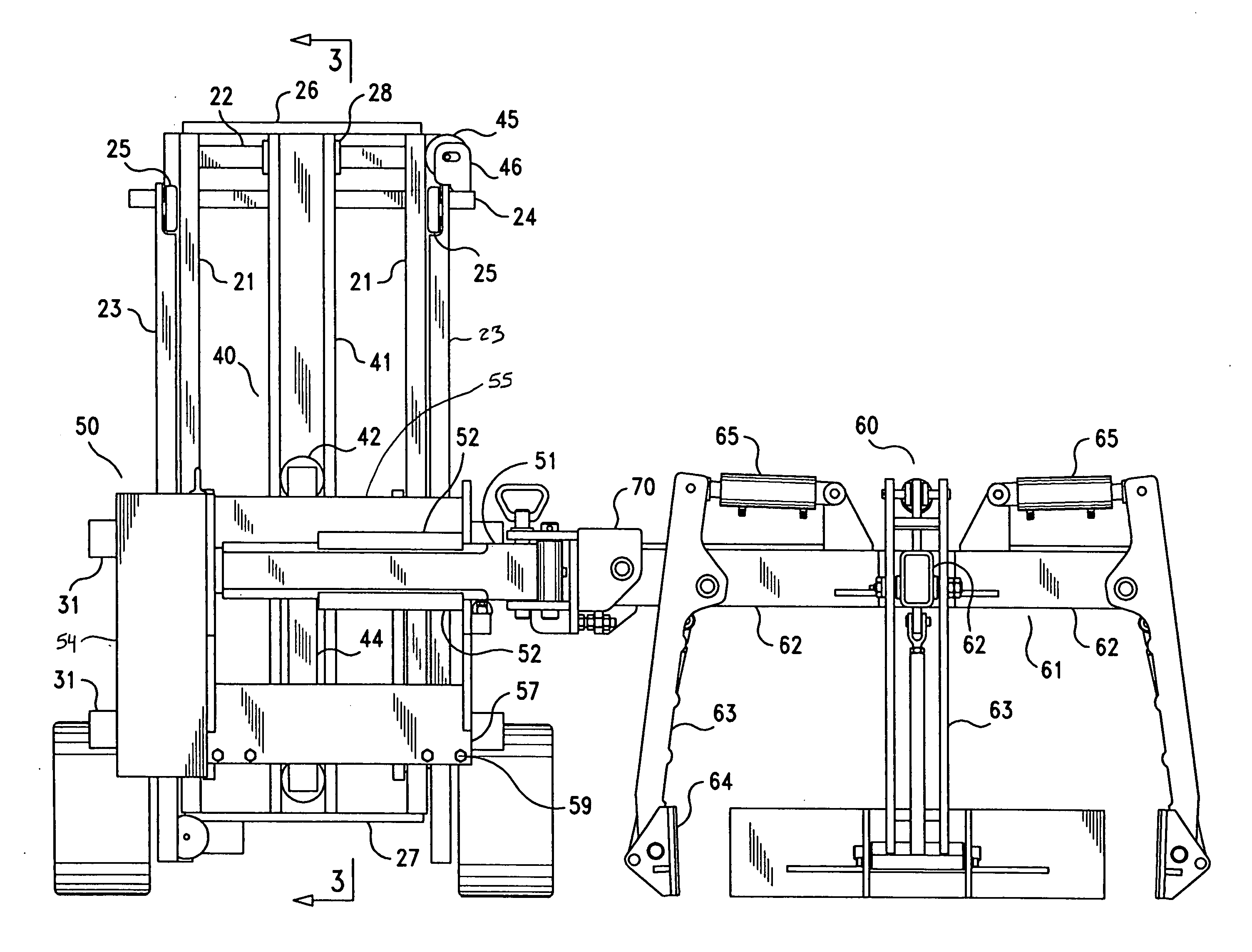
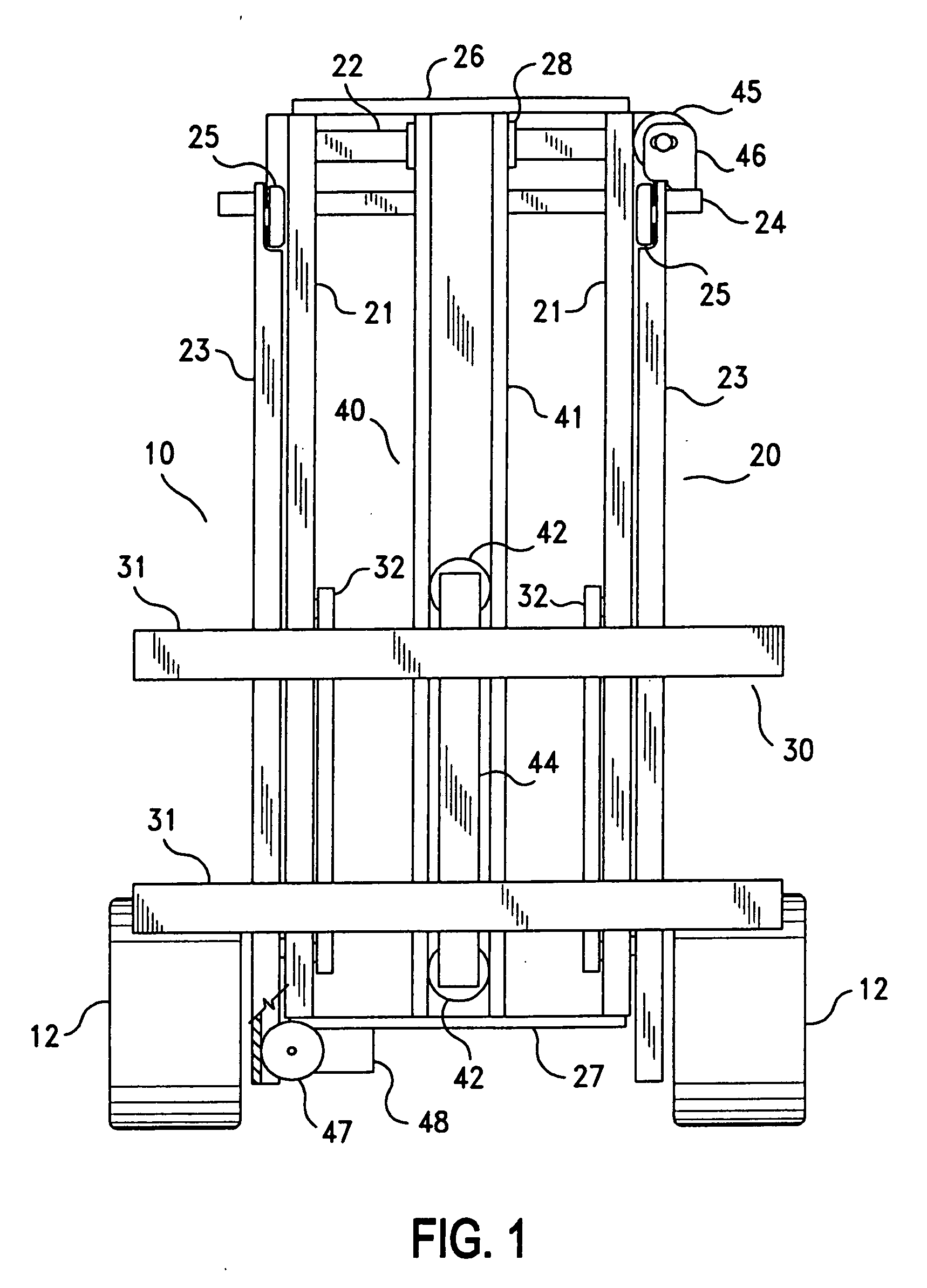
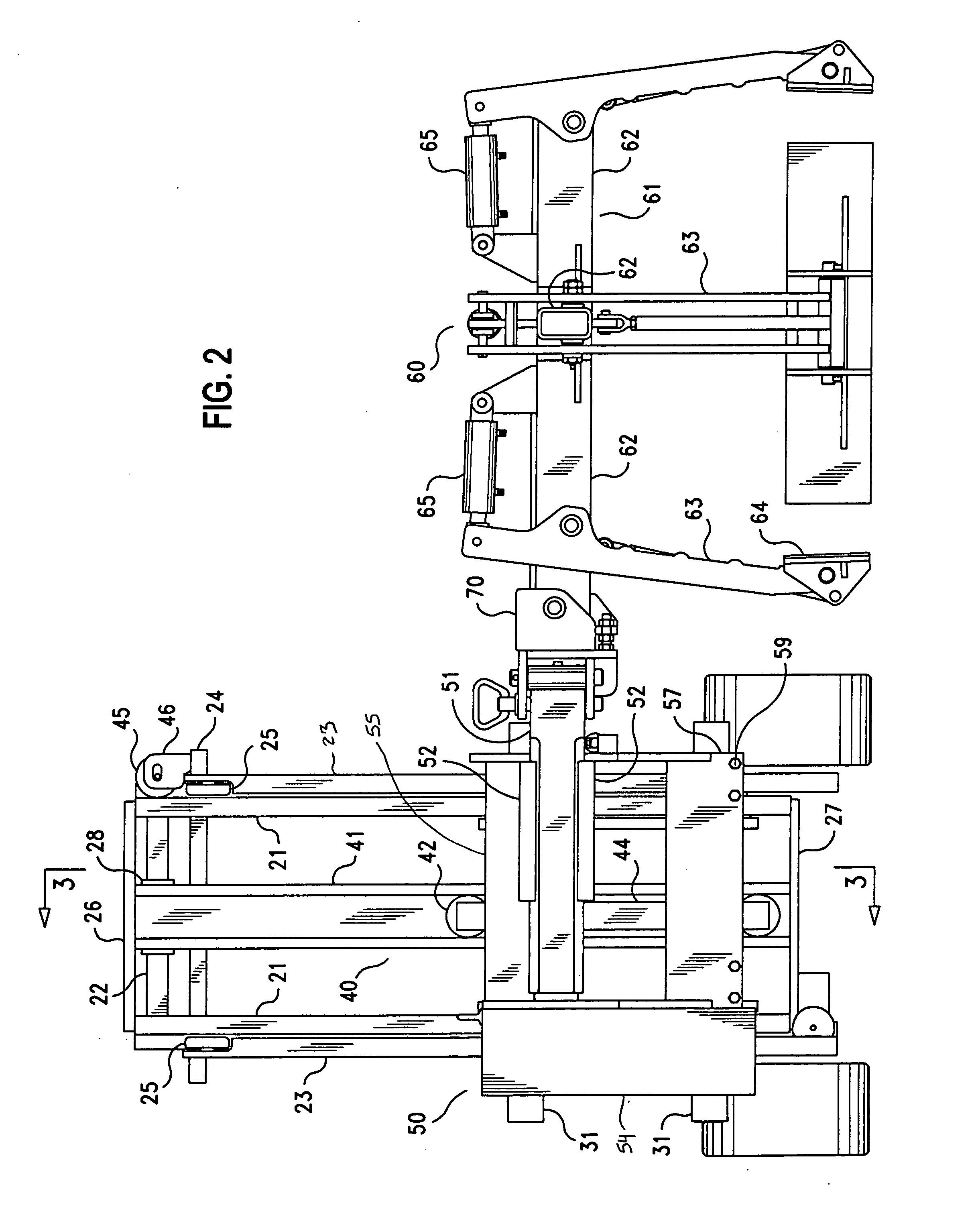
[0037]FIGS. 1-4 illustrate a first embodiment of a lift truck 10 according to the present invention. FIGS. 1 and 4 show the lift truck 10 without any attachments mounted on it, while FIGS. 2 and 3 illustrate the lift truck 10 equipped with a side shifter 50 and a clamping apparatus 60 for grasping a load. As shown in these figures, the lift truck 10 has a body 11 supported by a plurality of wheels 12 (four in the present embodiment). A mast 20 is mounted on the front of the body 11 in a conventional manner so that the angle of the mast 20 with respect to the vertical can be adjusted, and a carriage 30 is supported by the mast 20 for vertical movement along the mast 20. The illustrated mast 20 is what is commonly referred to as a two-stage mast, but it may instead be a one-stage mast or a mast with three or more stages. The overall structure of the mast 20 may be conventional. It includes a pair of inner channels 21, which are uprights disposed in parallel on opposite widthwise sides...


PUM


Abstract

A lift truck includes a guide member secured to a mast of the lift truck and a guided member secured to a carriage vertically movable along the mast. The guided member engages with the guide member to resist twisting moments acting on the carriage and enable the carriage to move smoothly along the mast. A lift truck attachment for mounting on a lift truck includes a latching member which can restrict movement of the attachment with respect to the lift truck in a fore-and-aft direction of the lift truck.

Description

REFERENCE TO RELATED APPLICATIONS [0001] This application is a continuation-in-part of U.S. patent application Ser. No. 11 / 153,899 filed on Jun. 16, 2005, the disclosure of which is incorporated by reference, which claims the benefit of U.S. Provisional Application No. 60 / 580,719 filed on Jun. 21, 2004. This application also claims the benefit of U.S. Provisional Application No. 60 / 750,826 filed on Dec. 16, 2005, the disclosure of which is incorporated by reference.BACKGROUND OF THE INVENTION [0002] This invention relates to a lift truck, and particularly to a lift truck capable of being used with a clamping apparatus for grasping a load from two or more sides. [0003] A lift truck is a self-propelled vehicle equipped with a movable frame, referred to as a carriage, which can be raised and lowered along an upright mast. Various attachments, such as forks or clamps for supporting or grasping a load, can be mounted on the carriage so that the lift truck can raise and lower the load. [0...

Claims


Application Information

Patent Timeline
IPC IPC(8): B66F9/06
CPCB66F9/188B66F9/148
Inventor TYGARD, EDWARD
Owner TYGARD MACHINE & MFG
Why Eureka
Eureka Blog
Learn More