Eureka AIR delivers breakthrough ideas for toughest innovation challenges, trusted by R&D personnel around the world.

Lock system

a technology of locking system and lock body, which is applied in the field of locking system, can solve the problems of difficult carrying of assembly work and producing nothing in return, and achieve the effects of facilitating remarkably the assembly work of component parts, preventing separation and facilitating assembly of housing and slide member

Active Publication Date: 2009-02-17
PIOLAX CO LTD
View PDF3 Cites 3 Cited by
  • Summary
  • Abstract
  • Description
  • Claims
  • Application Information

AI Technical Summary

Benefits of technology

[0008]According to a second aspect of the invention, there is provided the lock system according to the first aspect of the invention, further including an elastic locking portion which can be inserted into an insertion hole in the housing but which prevents a dislodgement thereof in an opposite direction, wherein the elastic locking portion is provided at the one end portion of the slide member.
[0012]Consequently, due to the reason that the slide member which connects the housing side which includes the latch and the spring to the manual operation unit side is molded into the molded part from the synthetic resin, since the housing side and the slide member side oscillate in no case freely relative to each other, it is possible to eliminate the situation where the relative postures of the component parts are changed during transportation, which is inherent in the conventional lock system. Consequently, there occurs no case where the component parts get entangled with other parts to such an extent that the disentanglement thereof from the other part becomes impossible or the component parts have to be realigned properly when they are assembled on to the glove box side, thereby making it possible to facilitate remarkably the assembling work of the component parts on to the lid of the glove box.
[0013]In the second aspect of the invention, since there occurs no inadvertent separation of, in particular, the housing and the slide member due to the existence of the elastic locking portion, the handling, transportation and assembling of the housing and the slide member on to the lid becomes convenient remarkably.
[0014]In the third aspect of the invention, the assembling of the housing and the slide member is facilitated by the guide surface of the elastic arm, and the separation of the housing and the slide member can be prevented in a more ensured fashion by the vertical lock surface.
[0015]In the fourth aspect of the invention, since the rotation permitting portion of the slide member exhibits the notched recess shape and the circumferential edge of the rotation permitting portion which lies on the side facing the rotation preventing portion is made to be smaller in height than the projecting height of the external boundary wall which extends from the vicinity of the rotation preventing portion to the notched recess shape, the stable sliding of the slide member is ensured while securing the continuity on the one end portion side of the slide member, thereby making it possible to cause the abutment lower end portion of the latch to be translated smoothly into the rotation permitting portion which exhibits the notched recess shape.
[0016]In the fifth aspect of the invention, since the cross sectional shape of the slide member is twisted midway along the length thereof, the latch can be made smaller in size and lighter in weight, and although it is light in weight, the slide member can obtain a high rigidity and the sliding support, thereby making it possible not only to enhance the operation feeling of the lock system but also to reduce the thickness of the lid of the glove box.

Problems solved by technology

Due to this, since the relevant component parts get entangled with other parts to such an extent that the disentanglement thereof from the other parts becomes impossible or the postures of the three component parts have to be realigned properly when they are assembled on to the glove box side, the assembling work tends to become difficult to be carried with producing nothing in return.

Method used


Image

  • Lock system
  • Lock system
  • Lock system

Examples


Embodiment Construction

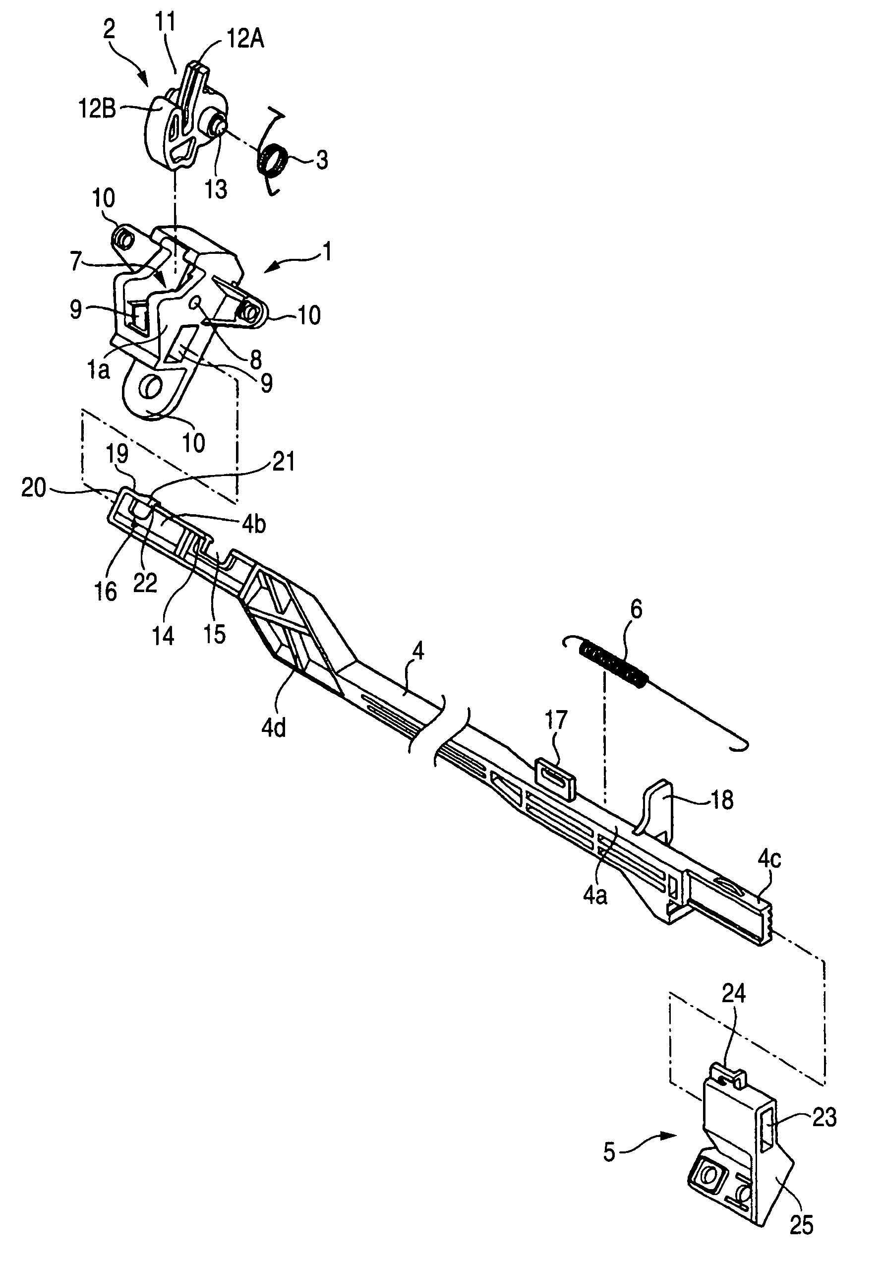
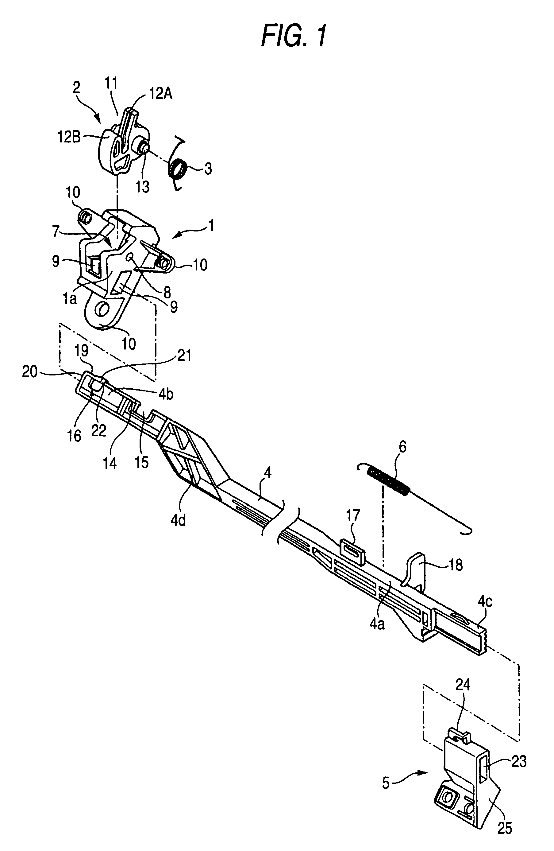
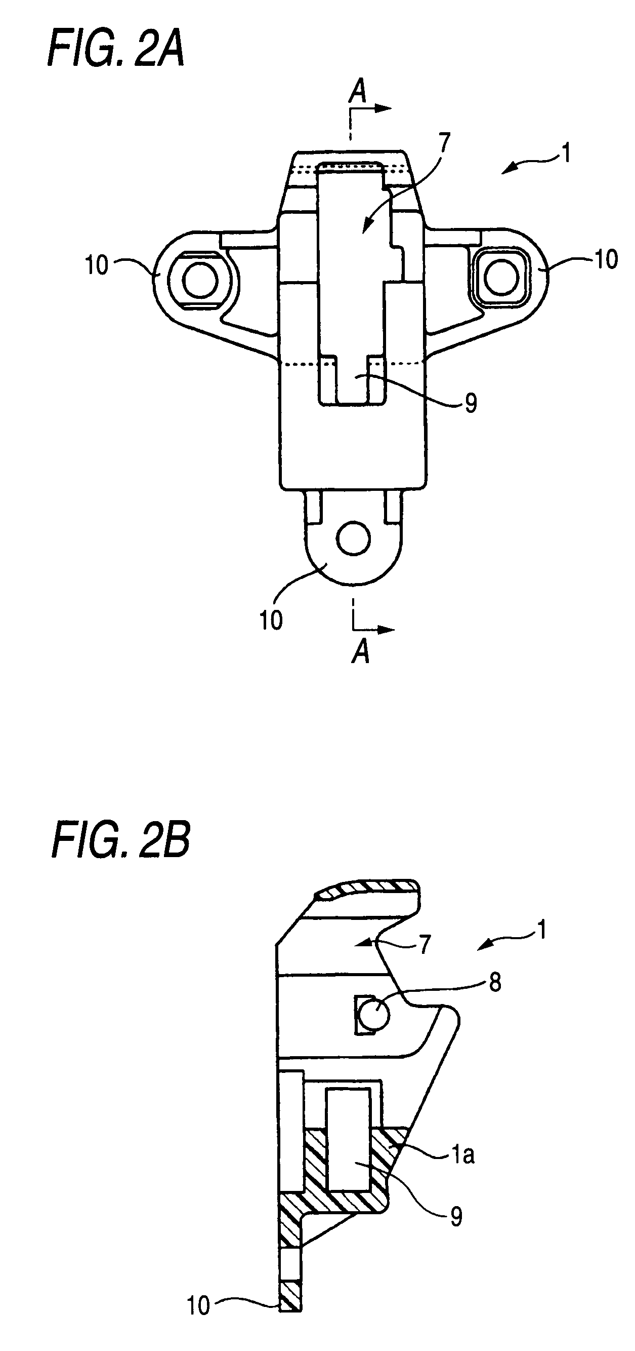
[0027]The invention is such as to particularly enable a lock system for a glove box or a lid thereof to be made up into a module so as to facilitate the assemblage of the lock system to a lid of a glove box by providing a lock system including a latch which is rotatably supported on a housing in such a manner as to be brought into engagement with and disengagement from a striker, a spring for biasing the latch in a direction in which the engagement of the latch with the striker is released, and a slide member which is rotatably supported on the housing in such a manner as to control the rotation of the latch, wherein the slide member is an integrated molded part which is molded from a synthetic resin and has provided at one end portion a rotation preventing portion which prevents a rotation of the latch in a biased direction and a rotation permitting portion which permits the rotation of the latch in the biased direction and provided at the other end portion thereof a driven portion...


PUM


Abstract

A lock system includes: a latch which is rotatably supported on a housing, and is brought into engagement with and disengagement from a striker; a spring for biasing the latch in a direction in which the engagement of the latch with the striker is released; a slide member which is rotatably supported on the housing, controls the rotation of the latch, and is an integrated molded part; a rotation preventing portion which prevents a rotation of the latch in a biased direction; a rotation permitting portion which permits the rotation of the latch in the biased direction; and a driven portion which links with a manual operation unit, wherein: the rotation preventing portion and the rotation permitting portion are provided at one end portion of the slide member; and the driven portion is provided at the other end portion of the slide member.

Description

BACKGROUND OF THE INVENTION[0001]1. Field of the Invention[0002]The present invention relates to a lock system for locking a glove box itself which is mounted on an instrument panel of a motor vehicle in such a manner as to be opened and closed or an independent lid of the glove box.[0003]2. Description of the Related Art[0004]Although not illustrated specifically, a conventional lock system of this type is made up of a housing which is fixed to a lid side of a glovebox, a latch which is rotatably supported on the housing in such a manner as to be brought into engagement with and disengagement from a striker, a spring for biasing the latch in a direction in which the engagement of the latch with the striker is released, a lock plate with a notched recessed portion which is slidably supported on the housing to control the rotation of the latch, an operation handle having an operation arm on a rear surface thereof, an L-shaped lever which rotates eccentrically by virtue of an operatio...

Claims


Application Information

Patent Timeline
Patent Type & Authority Patents(United States)
IPC IPC(8): E05C3/06E05B83/30E05C21/00
CPCE05B83/30E05C3/24E05B53/00Y10S292/23Y10T292/1082Y10T292/1047
Inventor NAJIMA, MASAHIRO
Owner PIOLAX CO LTD
Why Eureka
Eureka Blog
Learn More