
Apparatus for mounting accessories to pottery wheels

a technology for accessories and pottery wheels, applied in the field of pottery wheel accessories, can solve the problems of not precisely locating the holes in the same location, accessories may not fit on a particular pottery wheel, and work takes longer than one session

Inactive Publication Date: 2007-08-30
LESTER SAM
View PDF4 Cites 5 Cited by
  • Summary
  • Abstract
  • Description
  • Claims
  • Application Information

AI Technical Summary

Benefits of technology

[0009]In accordance with principles of the present invention, a porous bat may be used on a pottery wheel including a locating pin at a nominal location. The porous bat includes an elongated hole at a location corresponding to the nominal location. The elongated hole is ada

Problems solved by technology

Wheel manufacturers do not, however, precisely locate the holes in the same location.
Because the holes in the wheel head may not be located precisely, accessories may not fit on a particular pottery wheel without some means to adjust the location of the accessory to compensate for the variations in the location of the holes.
Often the work takes longer than one session and / or when completed needs to remain undisturbed until it dries.
This leads to uneven drying.
However, because the holes in different pottery wheels are not located in precisely the same location, such a bat may not fit onto the bolts on a different pottery wheel.
However, for the same reason, the commercially produced bat may not fit onto the bolts in a particular pottery wheel.
In addition, plaster is soft and brittle.
However, such locating pins are more expensive than the ¼-20 hex head bolts.

Method used


Image

  • Apparatus for mounting accessories to pottery wheels
  • Apparatus for mounting accessories to pottery wheels
  • Apparatus for mounting accessories to pottery wheels

Examples


Embodiment Construction

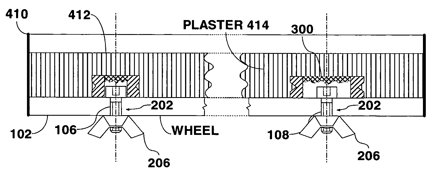
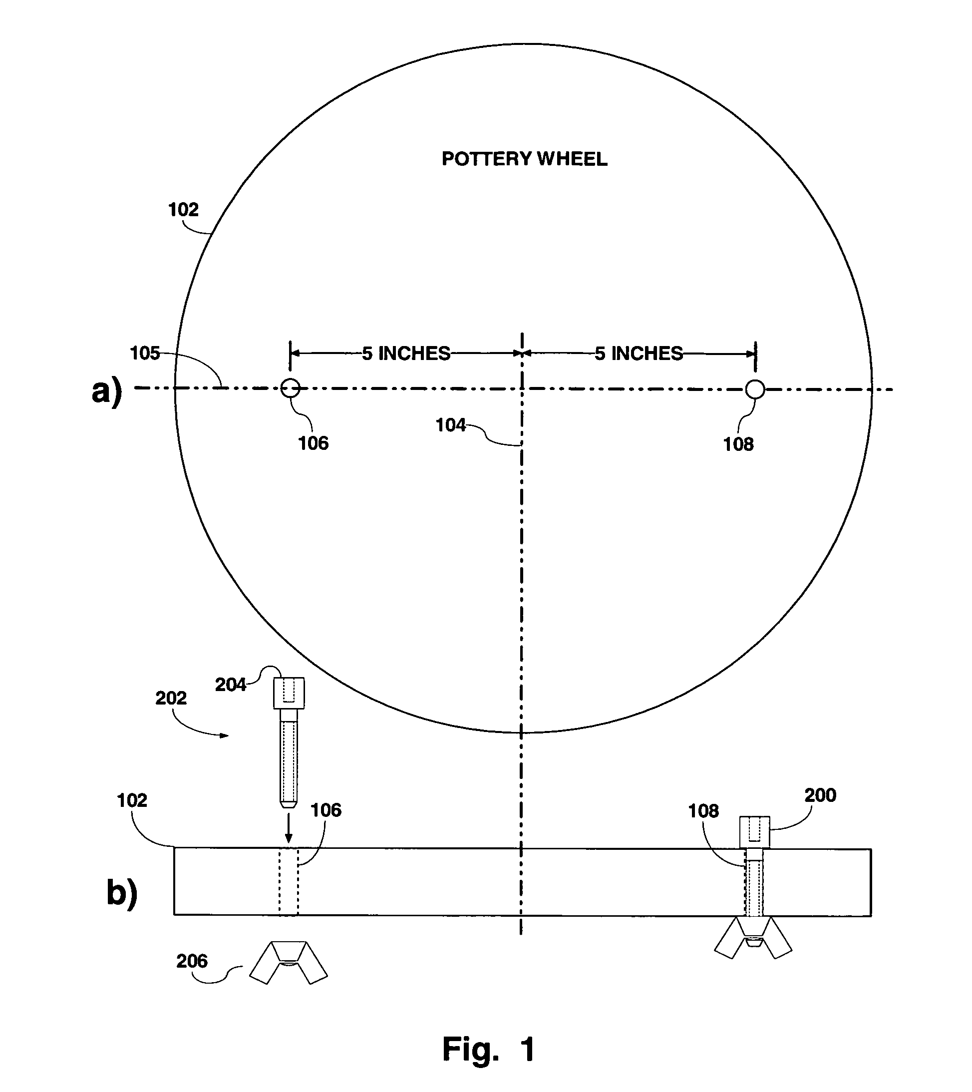
[0020]FIG. 1 is a diagram of a pottery wheel 102 in which holes have been drilled for locating pins at nominal locations. FIG. 1a illustrates a top view of a pottery wheel 102 and FIG. 1b illustrates a side view of the pottery wheel 102. Two holes, 106 and 108 are drilled through the pottery wheel 102 nominally along a diameter 105 and at respective radii of 5 inches. As described above, the holes 106 and 108 are generally drilled by the pottery wheel manufacturer but sometimes are drilled by the owner of the pottery wheel. Thus, while the holes are nominally at 5 inch radii along a diameter, there may be a relatively wide tolerance around that nominal location. Respective bolts 202, having a head 204, are inserted into the holes 106,108, and secured there with a nut, such as a wing nut 206. This is illustrated in FIG. 1b. The bolt head 204 acts as a locating pin 200 on the surface of the pottery wheel 102.

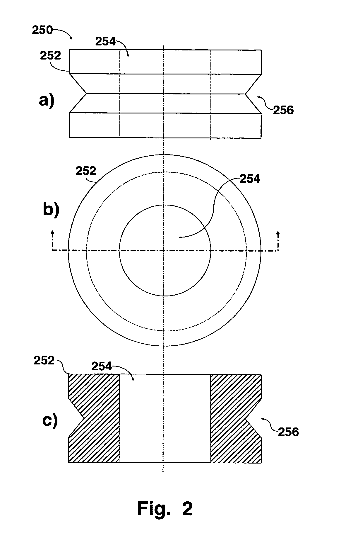
[0021]FIG. 2 is a diagram of a round collar 250 adapted to operate with the l...


PUM

PropertyMeasurementUnit
Radiusaaaaaaaaaa
Dimensionaaaaaaaaaa
Abrasion resistanceaaaaaaaaaa

Abstract

A porous bat may be used on a pottery wheel including a locating pin at a nominal location. The porous bat includes an elongated hole at a location corresponding to the nominal location. The elongated hole is adapted to slidably fit over the locating pin. The hole has a first axis with a dimension sized to fit over the locating pin and a second axis with a dimension larger than the first dimension to compensate for variations in the location of the locating pin on the pottery wheel.

Description

FIELD OF THE INVENTION[0001]The present invention relates to pottery wheel accessories, and more specifically to apparatus for mounting such accessories to pottery wheels.BACKGROUND OF THE INVENTION[0002]Potters often use pottery wheels to make pottery. To facilitate productivity, attachments, including trimming apparatuses, fixtures to hold the pottery during fabrication, trimming, shaping and decorating, and in particular bats, are often used. Currently, there are a variety of mechanical methods used to mount these attachments on a pottery wheel, also called a wheel head. One of the most common is to use bolt-heads as locating pins mounted in holes drilled at nominally standard locations in the pottery wheel. More specifically, the pottery wheel has holes drilled at points nominally along a diameter at a radius of, for example, 5 inches. Bolts having a specified head size, e.g. ¼-20 hex-head bolts, are mounted in the holes. Wheel manufacturers do not, however, precisely locate the...

Claims


Application Information

Patent Timeline
IPC IPC(8): B28B1/00B28B17/00
CPCB28B1/02B28B7/0014B28B1/025
Inventor LESTER, SAM
Owner LESTER SAM
Learn More