Method and system for locking execution plan during database migration

Inactive Publication Date: 2007-09-13
IBM CORP
View PDF3 Cites 36 Cited by
  • Summary
  • Abstract
  • Description
  • Claims
  • Application Information

AI Technical Summary

Problems solved by technology
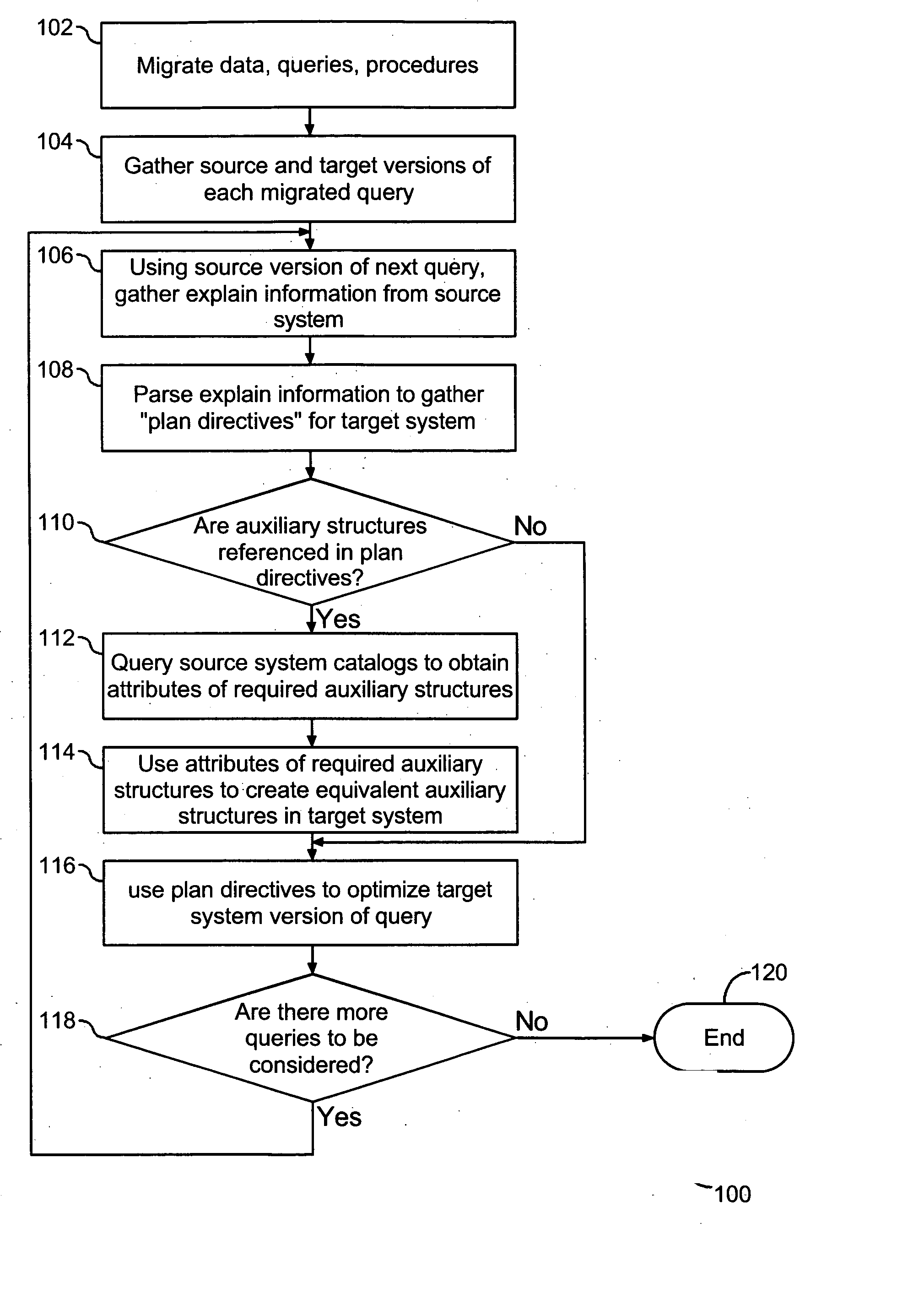
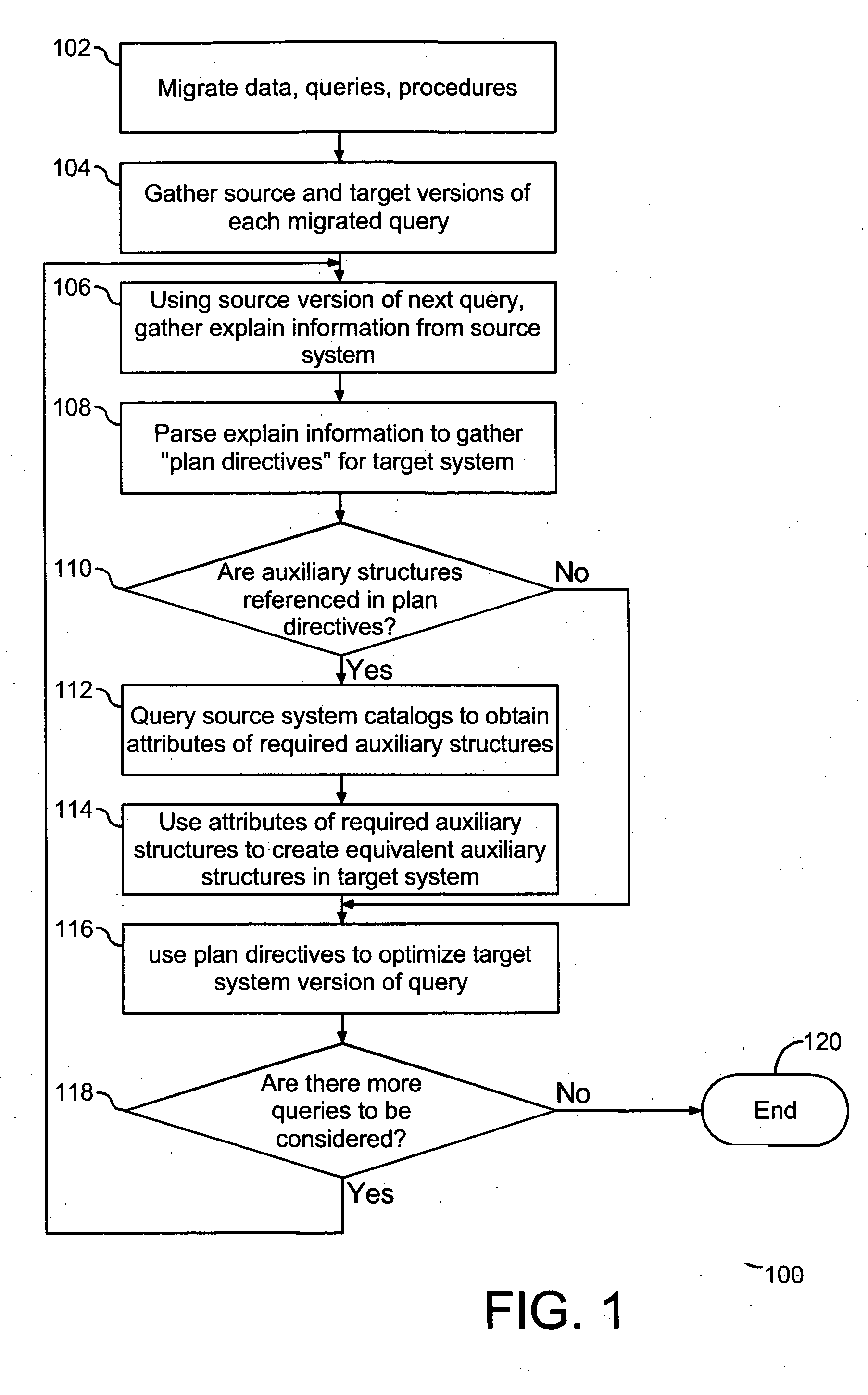
The prior art processes for migrating a database from a source system to a target system do not address how to in

Method used


Image

  • Method and system for locking execution plan during database migration
  • Method and system for locking execution plan during database migration
  • Method and system for locking execution plan during database migration

Examples


example 1

oracle Table definitions

create table T1 (I1 number(38), I2 number(38))

create table T2 (I3 number(38), I4 number(38))

create unique index T213 on T2(I3);

Oracle Query definition

select *

from T1, T2

where T1.I1=T2.I3 and T1.I4>5;

[0023] Example 2 shows equivalent DB2 definitions for the Oracle tables defined in Example 1. It also shows the DB2 version of the Oracle query defined in Example 1. Although it is not the case in general, in this example, the migrated DB2 query has the same syntax as the Oracle query.

example 2

[0024] DB2 Table definitions

create table T1 (I1 integer, I2 integer)

create table T2 (I3 integer, I4 integer)

DB2 Query definition

select *

from T1, T2

where T1.I1=T2.I3 and T1.I4>5;

[0025] Example 3 shows the Oracle explain statement used to obtain a description of the execution plan chosen by the Oracle optimizer for the query of Example 1.

example 3

explain plan for STATEMENT_ID=‘TEST’

select *

from T1, T2

where T1.I1=T2.13 and T1.I4>5;

[0026] Oracle places explain statement results in a special table called a plan table. An explain statement is a command presented to the optimizer requesting explain information. All databases have explain statements, but may be presented in different formats. For example, Oracle presents explain statements in a table format, but other databases may present the explain statement in different formats. Each row deposited in the plan table corresponds to a specific operator used in an Oracle execution plan. The most significant fields of the table are the OPERATION, OBJECT_NAME, OPTION, ID, and PARENT_ID fields. The OPERATION field gives the name of the execution plan operator. The OBJECT_NAME field defines what object the operator works on, or with. The OPTION field gives more detailed information about the operation performed by the operator. The ID and PARENT_ID fields are used to indicate h...


PUM


Abstract

A method and system are provided for optimizing a query migrated from a source database system to a possibly dissimilar target database system, wherein the execution plan chosen for the migrated query is communicated from the source database system. Explain facilities of the source database system are used to gather information describing the execution plan used in the source database system for the migrated query. The explain information is then used to obtain plan directives for communicating the execution plan to the optimizer of the target system. If the obtained plan directives require auxiliary data structures, the source system catalogs are queried to determine the attributes of these auxiliary structures. These attributes are then used to create equivalent auxiliary structures in the target system. The migrated query is then optimized using the obtained plan directives, thus enabling database migration to preserve the investment made in tuning the execution plan on the source system

Description

BACKGROUND OF THE INVENTION [0001] 1. Technical Field [0002] This invention relates to migration of databases. More specifically, the invention relates to preserving execution plans present in a source database to a target database. [0003] 2. Description of the Prior Art [0004] A database is a collection of information organized to enable a computer program to quickly select desired data. Traditional databases are organized by fields, records, and files. A field is a single piece of information. A record is one complete set of fields. A file is a collection of records. To access information from a database, a collection of programs are used to enable entering, organizing, and selecting data in a database. Relational database systems store large amounts of data, including business data that can be analyzed to support business decisions. Data records within a relational database management system in a computing system are maintained in tables, which are a collection of rows all having...

Claims


Application Information

Patent Timeline
IPC IPC(8): G06F17/30
CPCG06F17/30463G06F16/24542
Inventor MIAO, BINGJIESIMMEN, DAVID E.
Owner IBM CORP
Why Eureka
Try Eureka