

Optimized SQL code generation
- Summary
- Abstract
- Description
- Claims
- Application Information
AI Technical Summary
Benefits of technology
Problems solved by technology
Method used
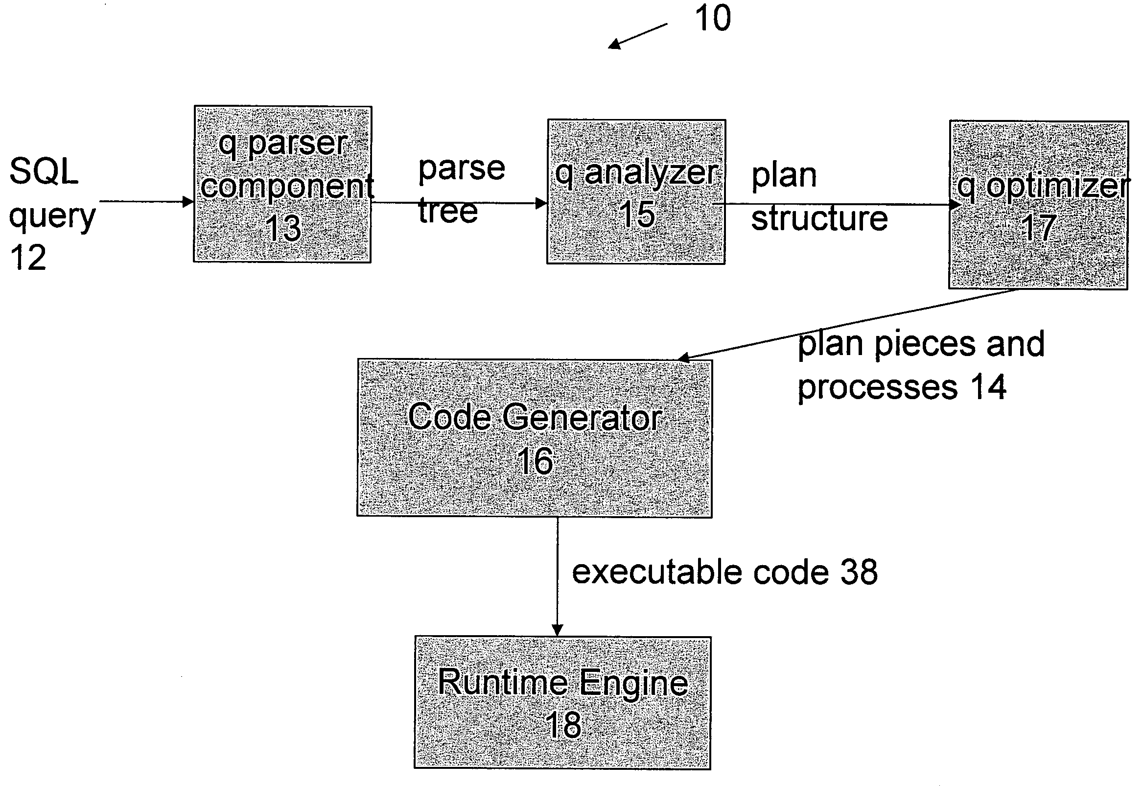
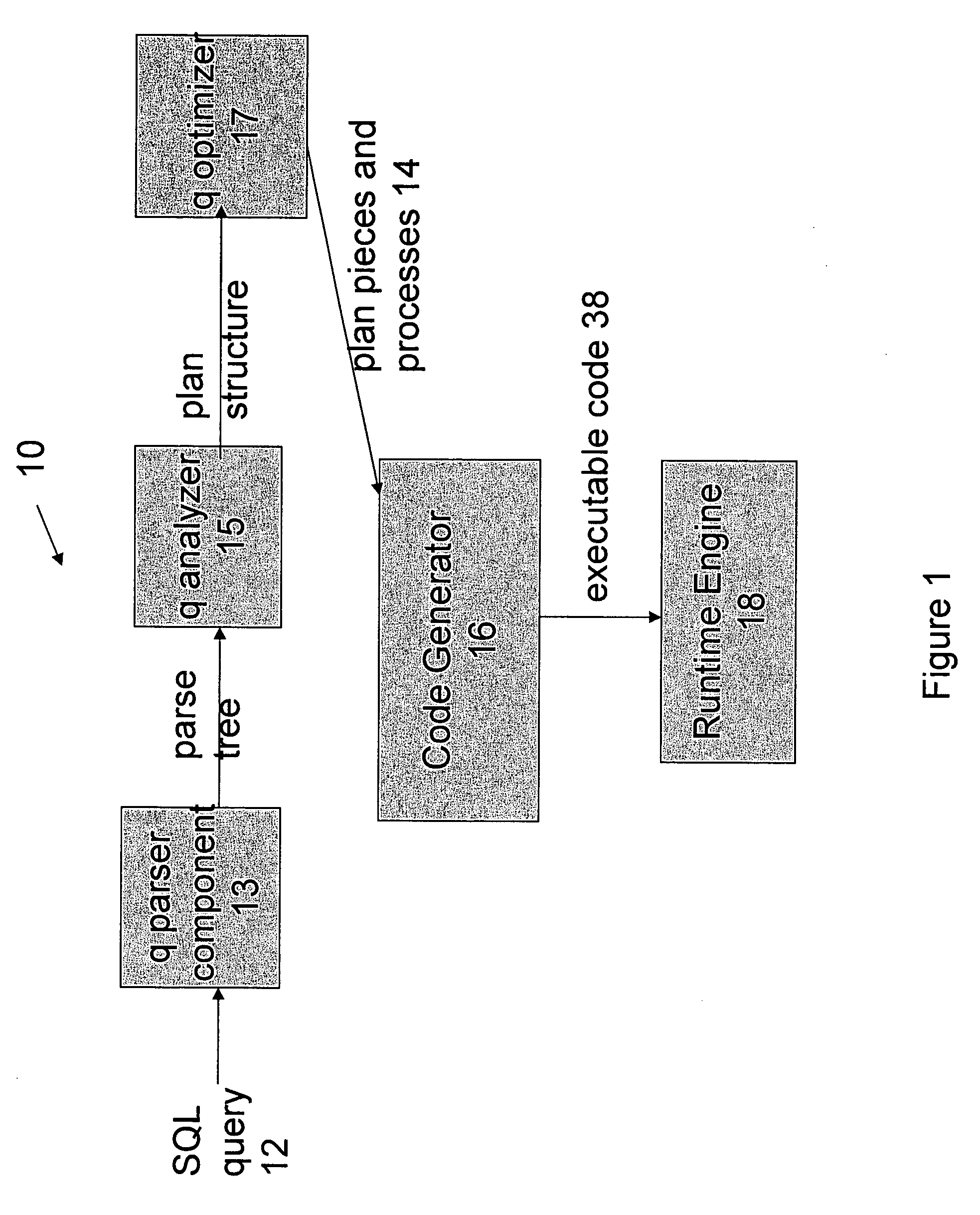
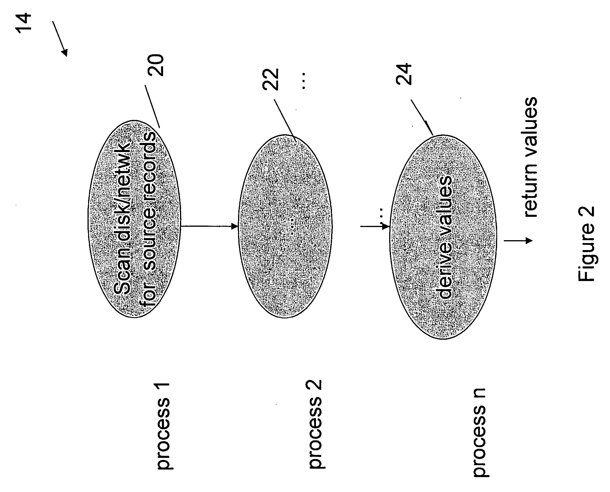
Image

Examples
example
The following SQL Statements create and populate a table: create table ps (n numeric(20,2) not null, m numeric(20,4) not null); insert into ps values (25.10, 130.3000);
And this statement retrieves a computed value from the table:
select (n+m)+2*(n+m) from ps;
The two columns, n and m, have declared precisions of 20 decimal digits and are stored by the invention as 128-bit values. So, a C++ code fragment showing the record layout would be:
/ / Input data record structure.struct TScan 0 {CNumeric128 f1; / / column nCNumeric 128 f2; / / column m};
But, by virtue of the invention's tracking of actual column values, one knows that the data in column n requires only 4 decimal digits, and column m only 7 decimal digits. So, this is a good example to show the advantage of the invention. First, let's look at some C++ code fragments in the absence of this feature of the invention:
/ / Select result row, with wide 128-bit result column f0.struct TReturn 3 {CNumeric128 f0; / / wide expression re...
PUM
 Abstract
Description
Claims
Application Information