Check patentability & draft patents in minutes with Patsnap Eureka AI!

Roller die press

Inactive Publication Date: 2007-09-20
PROVO CRAFT & NOVELTY
View PDF99 Cites 28 Cited by
  • Summary
  • Abstract
  • Description
  • Claims
  • Application Information

AI Technical Summary

Benefits of technology

[0010] These and other advantages will become apparent from a reading of the following summary of the invention and description of the preferred embodiments in accordance with the principles of the present invention.

Problems solved by technology

In general, such machines were relatively bulky.
Conversely, the smaller crank operated machines are less stable, given their relatively smaller footprint when operating the machine.
In addition, because the machines were made to be more compact, the machines do not laterally support for the die and medium during the cutting process.

Method used


Image

  • Roller die press
  • Roller die press
  • Roller die press

Examples


Embodiment Construction

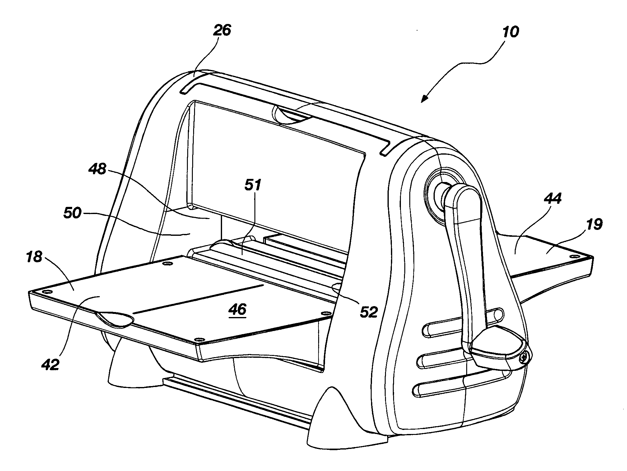
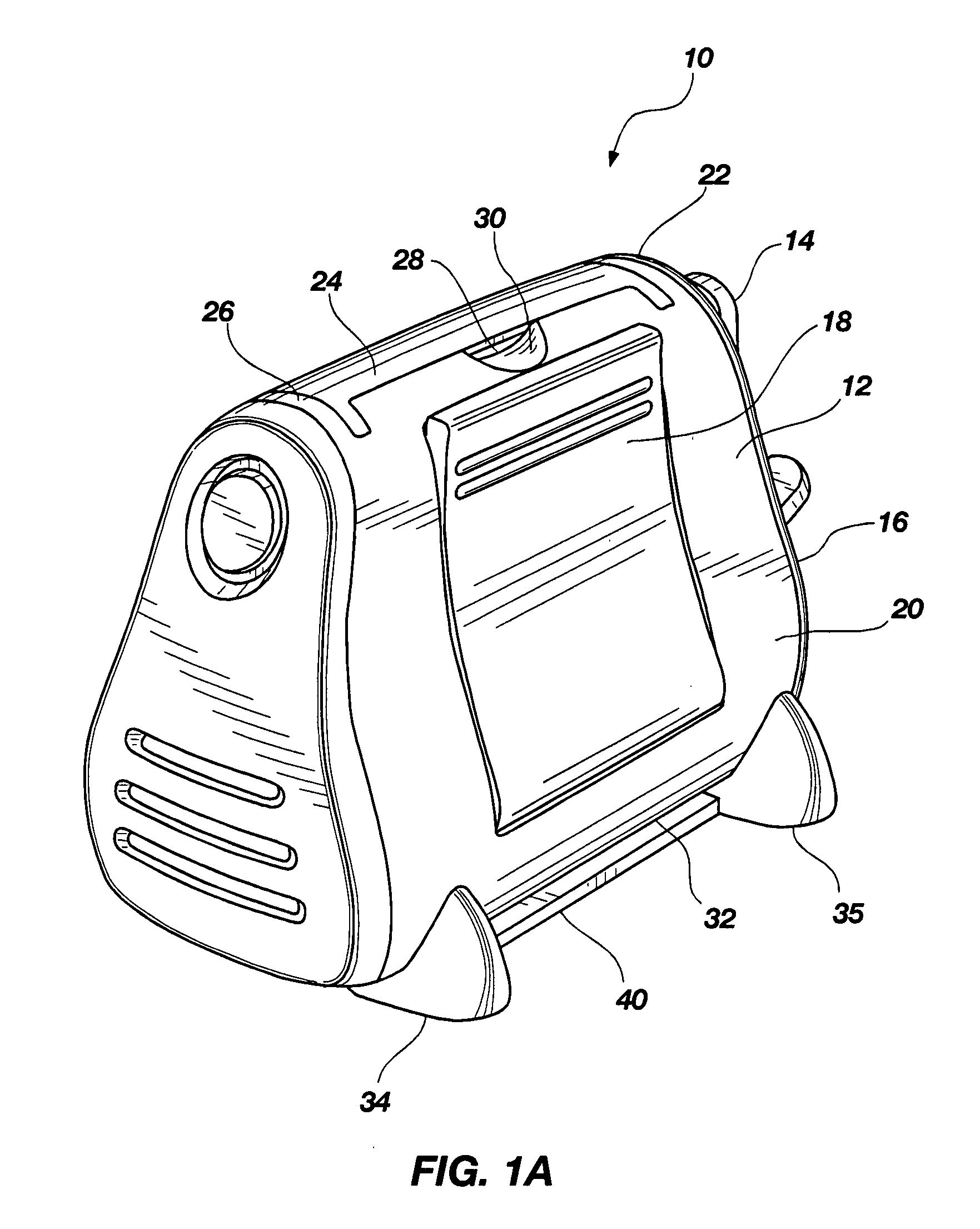
[0023]FIG. 1A is a perspective side view of a first embodiment of a roller-type die press, generally indicated at 10 for use with paper cutting dies, such as the types of cutting dies for cutting paper or other materials in sheet form known in the art (e.g., SIZZIX brand dies and SIZZLET brand dies). The die press 10 is comprised of a housing body 12 having a generally tear-drop shape. A crank handle 14 is provided on one end 16 of the die press 10 for turning cylindrically shaped rollers (described below). A pair of doors, only door 18 of which is visible in FIG. 1, are provided on either side 20 and 22 of the die press 10. A carry handle 24 is provided along the top 26 of the die press 10. The handle 24 is integrated into the top 26 of the die press 10 and retracts into a recess 28 when not in use. A pair of cut outs 30 is provided in the top 26 of the die press 10 for grasping the handle 24 and lifting the handle 24 relative to the top 26.

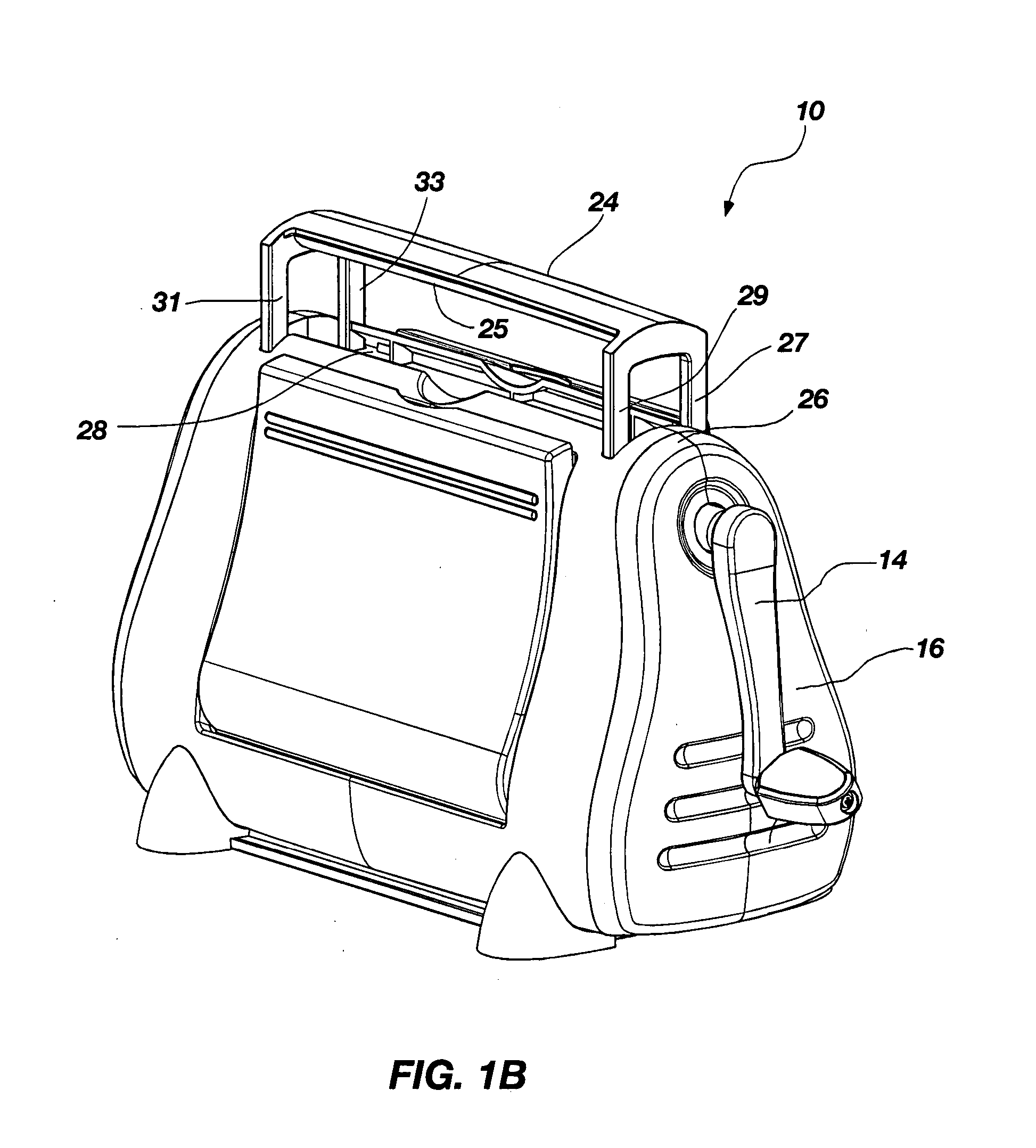
[0024] As shown in FIG. 1B, the handle 2...


PUM


Abstract

A roller press includes a housing to which upper and lower rollers are coupled. A crank handle is coupled to at least one of the upper and lower rollers. Rotation of the crank handle causes rotation of the rollers. Two doors that provide die support surfaces are coupled to the housing and are moveable between a closed position and an open position. A suction member is coupled to the bottom of the housing. The suction member is actuated by movement of the doors.

Description

CROSS-REFERENCE TO RELATED APPLICATIONS [0001] This application claims the benefit of U.S. Provisional Application No. 60 / 763,471, filed Jan. 30, 2006, entitled ROLLER DIE PRESS, which is hereby incorporated herein by reference in its entirety.BACKGROUND OF THE INVENTION [0002] 1. Field of the Invention [0003] The present invention relates generally to die presses used with dies for forming paper cut out patters, and more particular to a roller-type die machine. [0004] 2. Description of the Prior Art [0005] Die cuts are preformed pieces of paper or other die cuttable materials that are cut into a desired shape. For example, die cuts are often available in various shapes such as teddy bears, hearts, stars, etc. Multiple die cuts are usually packaged together for consumer purchase and may include die cuts formed from various colors of paper. [0006] The die cuts are formed by pressing a blade, which has been formed into the desired shape, against a sheet of paper or any other cuttable ...

Claims


Application Information

Patent Timeline
IPC IPC(8): B30B3/04
CPCB26F1/42B26D5/10
Inventor AYALA, GERRYHORITO, MICHAELALLAN, TYLER
Owner PROVO CRAFT & NOVELTY
Features
  • R&D
  • Intellectual Property
  • Life Sciences
  • Materials
  • Tech Scout
  • Unparalleled Data Quality
  • Higher Quality Content
  • 60% Fewer Hallucinations
Learn More