Multifunctional belaying device for a rope
- Summary
- Abstract
- Description
- Claims
- Application Information
AI Technical Summary
Benefits of technology
Problems solved by technology
Method used
Image
Examples
Embodiment Construction
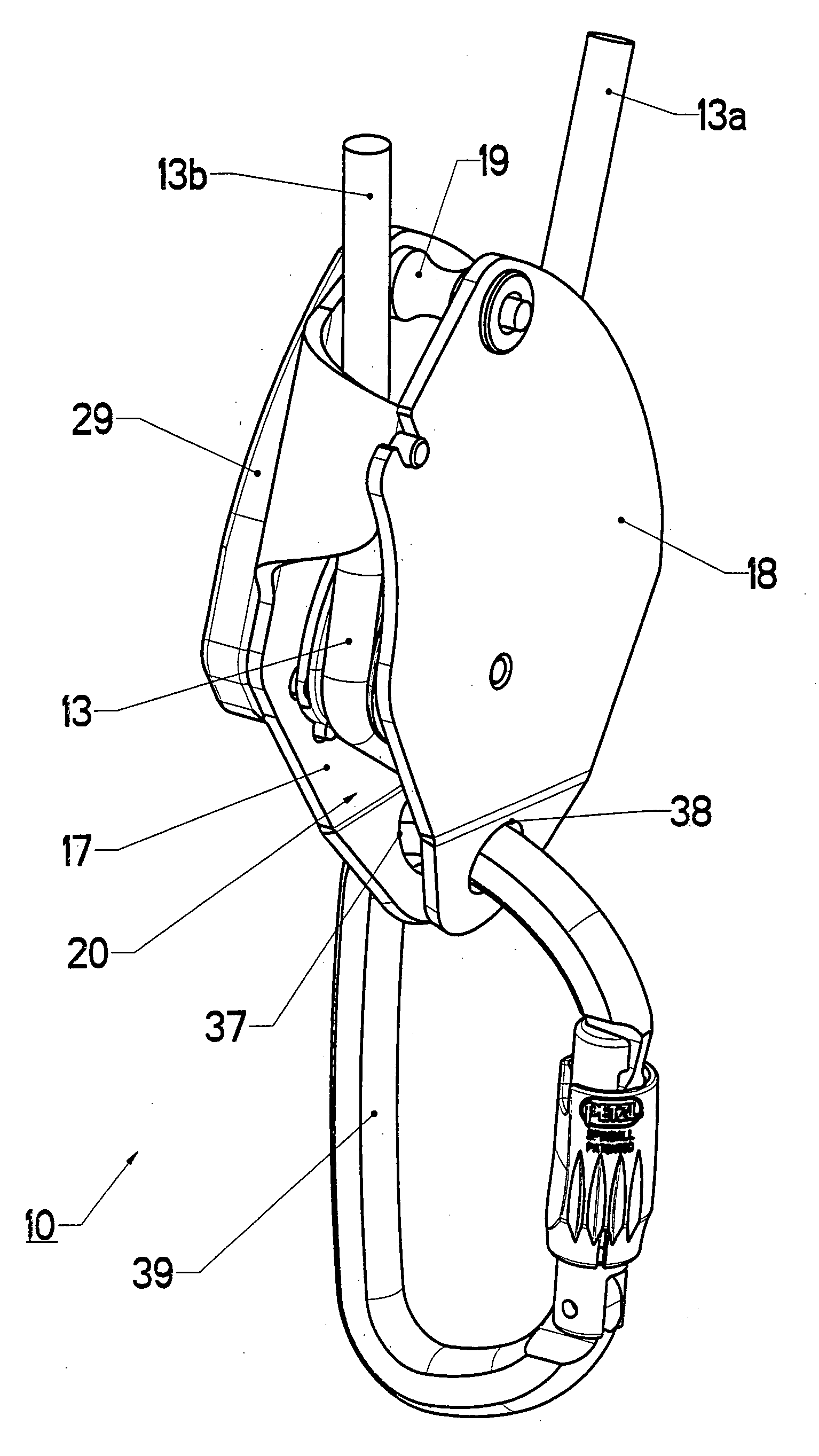
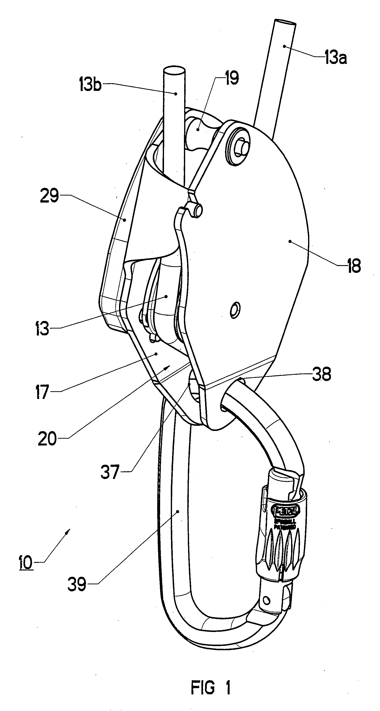
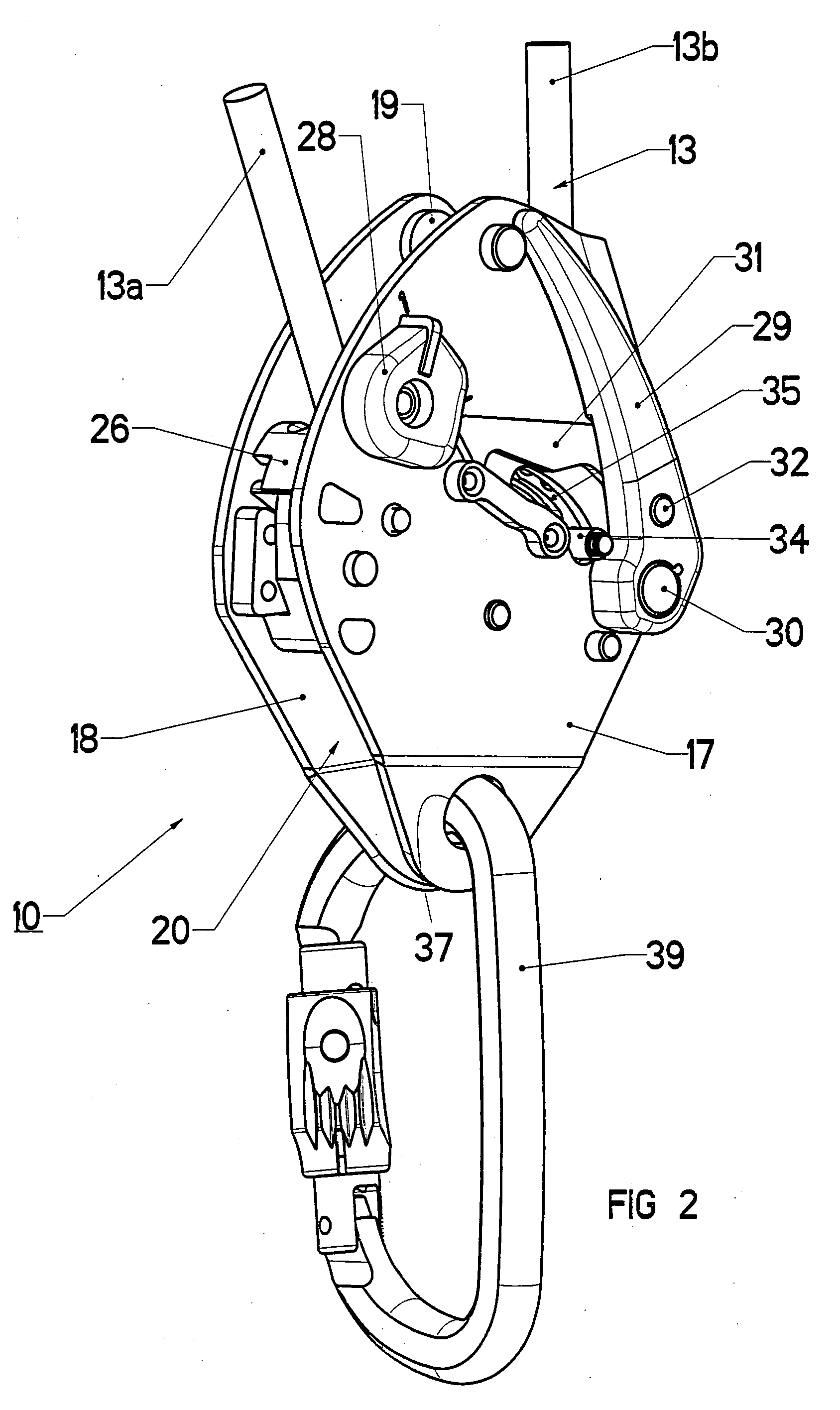
[0027]In FIGS. 1 to 13, a belaying device 10 for a rope comprises a blocking cam 11 having a peripheral sector provided with a groove 12 around which a rope 13 is wound in a half-turn. The cam 11 is mounted with limited rotation around a first fixed spindle-pin 14 and is able to move between a securing position corresponding to a blocking effect of the rope (FIG. 8) and a separated position corresponding to a releasing effect of the rope (FIG. 5).
[0028]In the securing position following a fall by the climber, the cam 11 is provided with a boss 15 designed to jam the rope 13 against a fixed stud 16. The stud 16 and spindle-pin 14 are secured by fixing means to the inside wall of a support plate 17 and are immobilized in rotation.
[0029]A retractable flange-plate 18 is mounted swiveling on a second spindle-pin 19 of the support plate 17 to occupy either an open position during the prior installation phase of the rope 13 around the cam 11 or a closed position (FIG. 2) to hold the rope 1...
PUM
 Abstract
Description
Claims
Application Information
 - R&D
- Intellectual Property
- Life Sciences
- Materials
- Tech Scout
- Unparalleled Data Quality
- Higher Quality Content
- 60% Fewer Hallucinations
Browse by: Latest US Patents, China's latest patents, Technical Efficacy Thesaurus, Application Domain, Technology Topic, Popular Technical Reports.
© 2025 PatSnap. All rights reserved.Legal|Privacy policy|Modern Slavery Act Transparency Statement|Sitemap|About US| Contact US: help@patsnap.com


