Multifunctional belaying device for a rope

a multi-functional, rope technology, applied in the field of rope belaying devices, can solve problems such as inability to drive, and achieve the effect of quick and precise unlocking of the cam

Inactive Publication Date: 2010-12-07
ZEDEL CORP
View PDF10 Cites 52 Cited by
  • Summary
  • Abstract
  • Description
  • Claims
  • Application Information

AI Technical Summary

Benefits of technology

[0009]The object of the invention consists in providing a versatile belaying device enabling quick and precise unlocking of the cam, regardless of the diameter and the degree of friction of the rope on the cam.

Problems solved by technology

The rope is not wound around the cam and can therefore not drive it as in a belaying and descending device for mountaineering.

Method used


Image

  • Multifunctional belaying device for a rope
  • Multifunctional belaying device for a rope
  • Multifunctional belaying device for a rope

Examples


Embodiment Construction

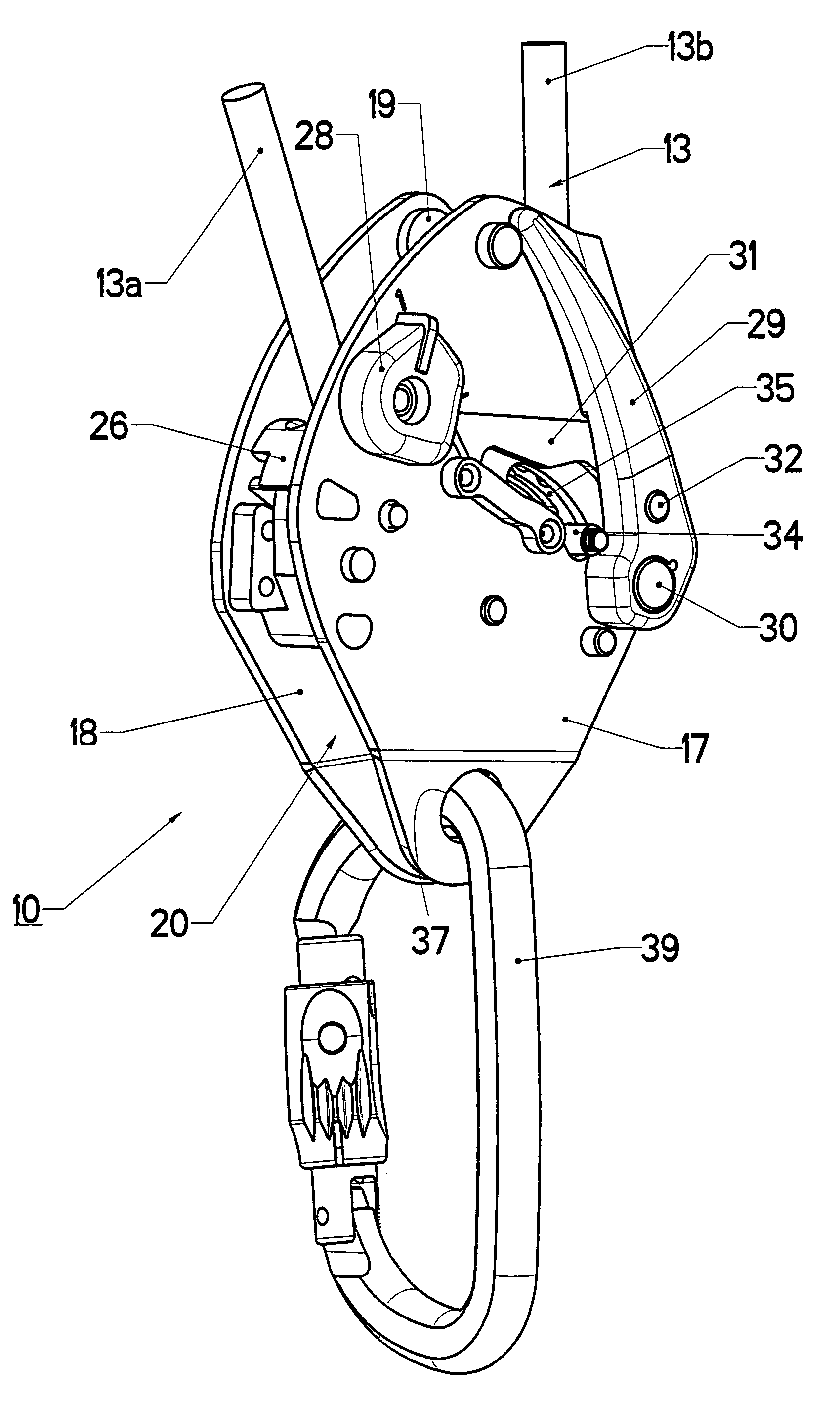
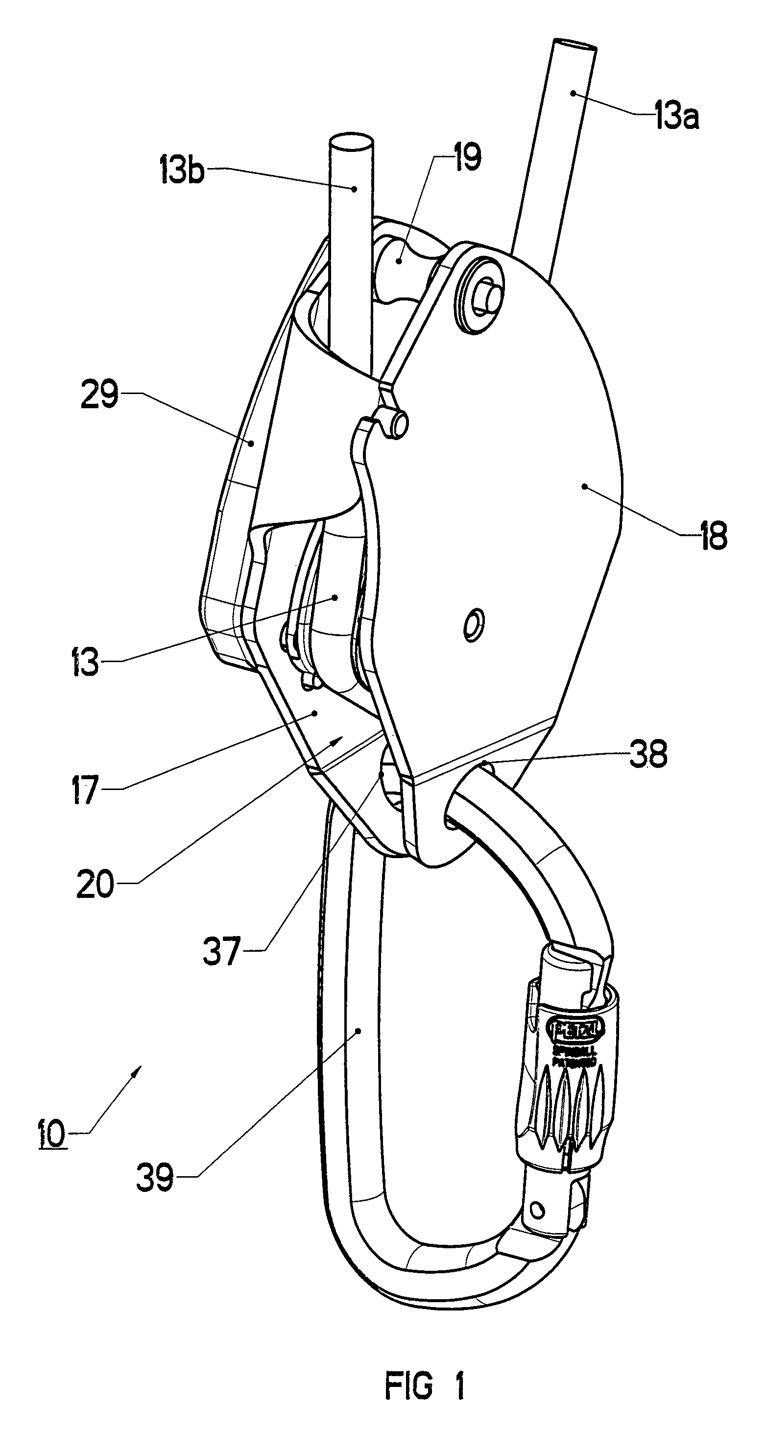
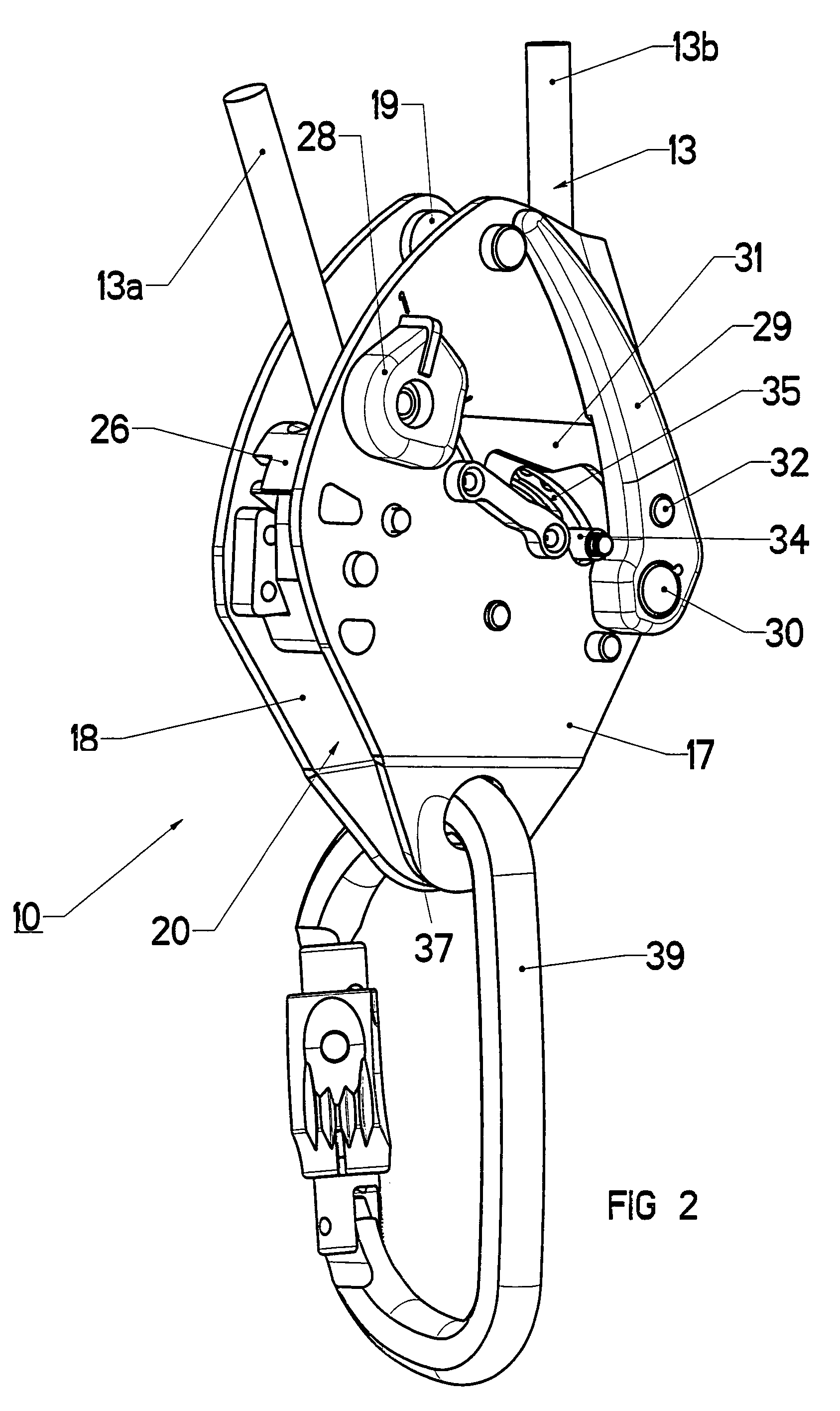
[0027]In FIGS. 1 to 13, a belaying device 10 for a rope comprises a blocking cam 11 having a peripheral sector provided with a groove 12 around which a rope 13 is wound in a half-turn. The cam 11 is mounted with limited rotation around a first fixed spindle-pin 14 and is able to move between a securing position corresponding to a blocking effect of the rope (FIG. 8) and a separated position corresponding to a releasing effect of the rope (FIG. 5).

[0028]In the securing position following a fall by the climber, the cam 11 is provided with a boss 15 designed to jam the rope 13 against a fixed stud 16. The stud 16 and spindle-pin 14 are secured by fixing means to the inside wall of a support plate 17 and are immobilized in rotation.

[0029]A retractable flange-plate 18 is mounted swiveling on a second spindle-pin 19 of the support plate 17 to occupy either an open position during the prior installation phase of the rope 13 around the cam 11 or a closed position (FIG. 2) to hold the rope 1...


PUM


Abstract

A belaying device for a rope comprises a cam able to rotate between a securing position corresponding to securing the rope by jamming effect against the stud and a separated position allowing the rope to run freely in the gap between the cam and the stud. The cam is associated with a triggering ratchet able to occupy either a locked position blocking the cam in the separated position or an unlocked position following a deliberate control action releasing said cam.

Description

BACKGROUND OF THE INVENTION[0001]The invention relates to a belaying device for a rope, comprising:[0002]a support plate equipped with a fixed stud,[0003]a cam mounted with limited rotation on the support plate around a first spindle-pin and having a peripheral sector around which the rope is wound, said cam being movable between a securing position corresponding to the rope being blocked by a jamming effect against the stud and a separated position enabling the rope to run freely in the gap between the cam and the stud.STATE OF THE ART[0004]The document EP-A-398819 describes a belaying device that is self-locking in the event of a sharp tension occurring. It comprises a cam mounted on a pivoting support plate equipped with a handle for manual release of the rope. A return spring of the support plate biases the cam to the open position allowing the rope to slide freely. The cam is provided with two braking surfaces, and the threshold for switching from the first locked position to t...

Claims


Application Information

Patent Timeline
Patent Type & Authority Patents(United States)
IPC IPC(8): A62B1/08
CPCA62B1/14A63B29/02
Inventor PETZL, PAULBROQUERIE, CHRISTIAN
Owner ZEDEL CORP
Why Eureka
Try Eureka