Single stage power factor corrected power converter with reduced AC inrush

a power converter and single-stage technology, applied in the direction of pulse technique, ignition automatic control, instruments, etc., can solve the problems of adding to the overall output power delivery capacity, and achieve the effects of reducing input ac current inrush, and improving output ripples

a power converter and single-stage technology, applied in the direction of pulse technique, ignition automatic control, instruments, etc., can solve the problems of adding to the overall output power delivery capacity, and achieve the effects of reducing input ac current inrush, and improving output ripples

US20070217235A1Inactive Publication Date: 2007-09-20ENERGY CONSERVATION TECH

Image

  • Single stage power factor corrected power converter with reduced AC inrush
  • Single stage power factor corrected power converter with reduced AC inrush
  • Single stage power factor corrected power converter with reduced AC inrush

Examples


Embodiment Construction

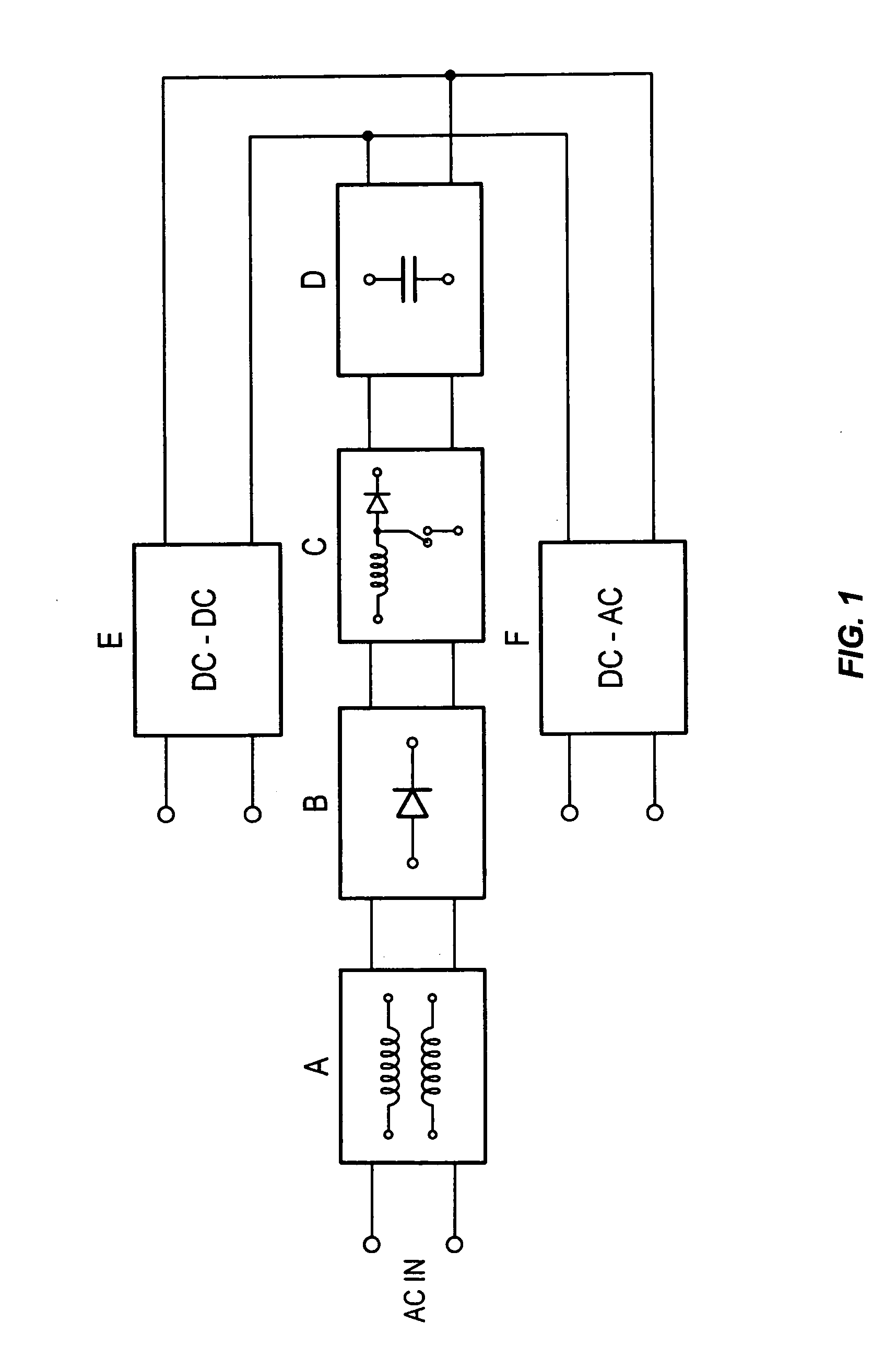
[0029]FIG. 1 illustrates in block diagram form a conventional 50 / 60 H AC power conversion scheme. Section A is a conducted EMI suppression circuit, section B is for AC-DC rectification, and section C is for obtaining high Power Factor, low Total Harmonic Distortion, and regulated DC power output by widely used boost converter topology. This regulated DC power is then fed to a high frequency DC-DC converter to power an output load with DC power or fed to a high frequency DC-AC inverter to power the output load with AC power. Detailed circuit descriptions of any individual section are not necessary since they are readily available in published literature and textbooks related to the art. Only the following relevant functions are explained for better understanding of the present improved single stage power converter. [0030] 1. Immediately following the application of AC power to the device and before the boost circuit of section C starts to operate, the initially uncharged electrolytic...


PUM


Abstract

The improved single stage power converter circuit topology substantially reduces EMI that is conducted to the AC line, reduces input AC current inrush, improves output ripples by the use of an auxiliary supply near zero crossings of the line AC voltage, provides Power Factors greater than 0.95, provides Total Harmonic Distortions less than 15%, and maintains constant power, including constant power in a non-linear output load. Further, this circuit topology provides output open and short circuit protections by reducing current stress in power components. This topology can also make the power source to appear as a fast-acting variable impedance source, an ideal source for powering an output load that has negative resistance characteristics such as gas discharge lamps.

Description

FIELD OF THE INVENTION [0001] This invention relates to single stage power conversion circuitry used in switched mode inverters and power converters. BACKGROUND OF THE INVENTION [0002] It is a problem in the field of power conversion that a 50 / 60 Hz AC power source is typically used in switched mode inverters and converters to provide the input power. The resultant power converter must then deal with both the efficiency of the power conversion operation and the quality of the output voltage, due to the noise generated by converting the 50 / 60 Hz AC power in the power conversion operation. [0003] In operation, after rectification of the input AC voltage, the power converter conventionally smoothes out the rectified DC sinusoid peaks by using large value electrolytic capacitors. This causes an enormous AC current inrush to the initially uncharged electrolytic capacitors when the power converter is first turned on. In addition, in high power applications, the power converters that use a...

Claims


Application Information

Patent Timeline
20 Sep 2007
Publication
US20070217235A1
IPC
H02M7/04
CPC
H02M1/425; Y02B70/126; H05B41/28; Y02B70/10
Inventors
QUAZI, FAZLE S.