Controller convenient for realizing ultra-low quiescent current of boost converter

A controller and pass-through control technology, applied in the power supply field, can solve problems such as reducing efficiency, increasing output voltage ripple, increasing frequency domain noise, etc., and achieves good transient response, ultra-low quiescent current, and good output ripple. Effect

Active Publication Date: 2021-11-26
六式格玛半导体科技(深圳)有限公司
View PDF8 Cites 3 Cited by
  • Summary
  • Abstract
  • Description
  • Claims
  • Application Information

AI Technical Summary

Problems solved by technology

[0003] For solutions with fixed switching frequency, the control circuit in the boost converter cannot meet enough quiescent current to ensure speed and bandwidth; for solutions with variable switching frequency The scheme will increase the output voltage ripple, reduce the efficiency, and increase the noise in the frequency domain; for the scheme adopting the switching frequency mixed design, more circuit modules will be introduced, and because different circuit designs are used in different modes, in For seamless transition from PWM mode to PFM mode, it is difficult to achieve ultra-low quiescent current;
[0004] For example, in the patent US10340796B2, additional circuit modules such as ADC and current estimator in the boost converter need to add additional circuits that consume quiescent current; for Buck design in patent CN201110076368.2 and similar buck design: design of low quiescent current synchronous rectification step-down DC-DC converter, using constant on-time (COT) architecture to control the buck converter, the architecture is in step-down The effect of low quiescent current can be achieved in the voltage converter, but this architecture cannot be directly applied to the boost converter to achieve the effect of low quiescent current
[0005]The existing technology can no longer meet the needs of people at the present stage. Based on the current situation, it is urgent to reform the technology of the existing boost converter to achieve the effect of ultra-low quiescent current

Method used


Image

  • Controller convenient for realizing ultra-low quiescent current of boost converter
  • Controller convenient for realizing ultra-low quiescent current of boost converter
  • Controller convenient for realizing ultra-low quiescent current of boost converter

Examples


Embodiment Construction

[0032] The following will clearly and completely describe the technical solutions in the embodiments of the present invention with reference to the accompanying drawings in the embodiments of the present invention. Obviously, the described embodiments are only some, not all, embodiments of the present invention. All other embodiments obtained by persons of ordinary skill in the art based on the present invention without making creative efforts fall within the protection scope of the present invention.

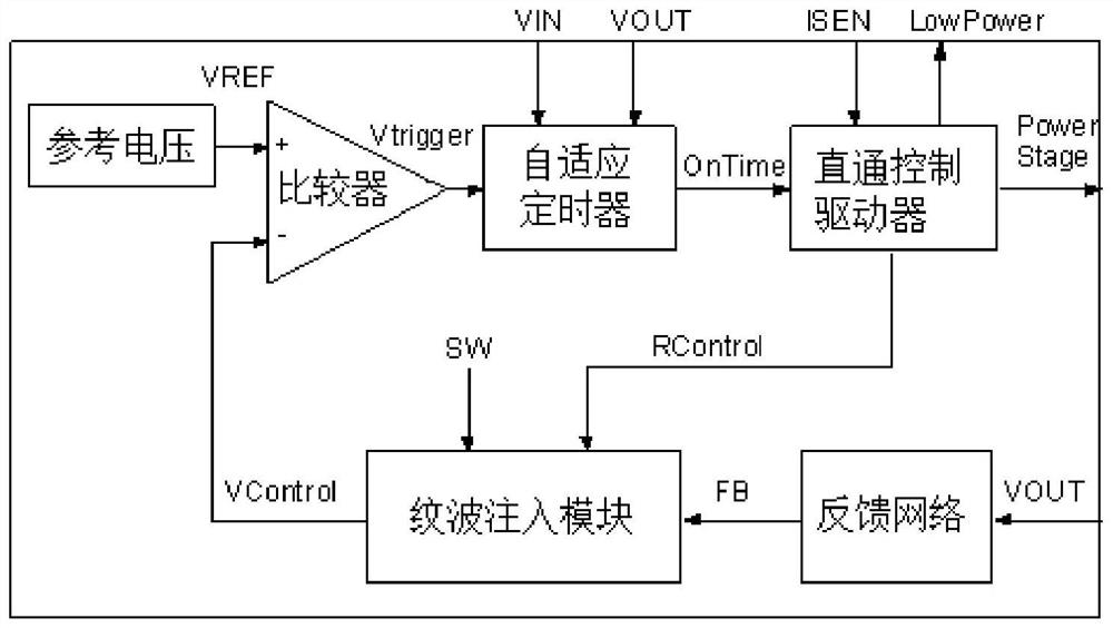
[0033] refer to figure 1 In one aspect, the present invention provides an optional embodiment of a controller, which is applied to a boost converter to achieve the effect of low quiescent current of the boost converter, and the controller includes: a comparator, an adaptive timer, Pass-through control driver, ripple injection block, feedback network and reference voltage;

[0034] The positive input terminal of the comparator is coupled to a reference voltage, and the referenc...


PUM


Abstract

The invention discloses a controller convenient for realizing ultra-low quiescent current of a boost converter, which comprises a comparator, a self-adaptive timer, a straight-through control driver, a ripple injection module, a feedback network and a reference voltage. The positive input end of the comparator is coupled with the reference voltage, the reference voltage provides a reference voltage signal VREF which is not sensitive to temperature, input voltage Vin, output voltage VOUT and load current, the negative input end of the comparator is coupled with the ripple injection module, the ripple injection module comprises a ripple generator and an inductive current simulator, the comparator outputs a signal Vtrigger, and the ripple injection module outputs a signal Vcontrol. The output end of the comparator is coupled with an adaptive timer. According to the invention, the controller adopts a constant on-time architecture to control the boost converter to maintain a constant switching frequency when the boost converter is in a heavy load, and the boost converter has ultra-low static power consumption when the boost converter is in a light load.

Description

technical field [0001] The invention relates to the technical field of a power supply, in particular to a controller for realizing ultra-low quiescent current of a boost converter. Background technique [0002] In converters, there are many different ways to control the boost converter in order to obtain a precise and stable output voltage. Common control designs for boost converters today include current-mode or voltage-mode control loops with fixed switching frequency (PWM), voltage-mode control loops with variable switching frequency (PFM), and Switching frequency mixed design control loop, use fixed switching frequency when the load current is large (heavy load), and automatically switch to variable switching frequency when the load current is small (light load); [0003] For the solution with fixed switching frequency, the control circuit in the boost converter cannot satisfy enough quiescent current to ensure the speed and bandwidth; for the solution with variable swi...

Claims


Application Information

Patent Timeline
IPC IPC(8): H02M1/088H02M3/158
CPCH02M1/088H02M3/158Y02B70/10
Inventor 刘若华其他发明人请求不公开姓名
Owner 六式格玛半导体科技(深圳)有限公司
Why Eureka
Try Eureka