Unlock instant, AI-driven research and patent intelligence for your innovation.

Turning control apparatus for vehicle

a technology for turning control and vehicles, applied in the direction of gearing, instruments, tractors, etc., can solve the problems of limited adhesive friction between the wheel and the road surface, difficult to run the vehicle in a straight line, and difficulty in generating yaw momentum at the vehicle, etc., to improve the turning ability and operation of the vehicle, improve the turning ability of the vehicle, and adequate yaw momentum

Active Publication Date: 2007-09-27
MITSUBISHI MOTORS CORP
View PDF12 Cites 10 Cited by
  • Summary
  • Abstract
  • Description
  • Claims
  • Application Information

AI Technical Summary

Benefits of technology

The present invention is a turning control apparatus for a vehicle that improves its ability to turn and operate. It uses sensors to detect the vehicle's turning direction and calculates the necessary yaw momentum to achieve smooth turning. The apparatus adjusts the driving torque between the left and right wheels to generate the required yaw momentum. It also takes into account the difference in rotation speed between the inside and outside wheels to accurately set the maximum yaw momentum value and improve the vehicle's turning ability. Overall, this invention enhances the vehicle's performance and operational efficiency.

Problems solved by technology

However, in reality, it is difficult to generate yaw momentum at a vehicle even if the driving torque difference between the left and right wheels is varied, because the capacity of traction (adhesive friction between the wheel and the road surface) is limited.
In this situation, it is difficult to run the vehicle in a straight line due to slip of the inside wheel, and then the degree of over-steering is increased in spite of adjusting the driving torque difference between the left and right wheels to prevent over-steering.

Method used


Image

  • Turning control apparatus for vehicle
  • Turning control apparatus for vehicle
  • Turning control apparatus for vehicle

Examples


Embodiment Construction

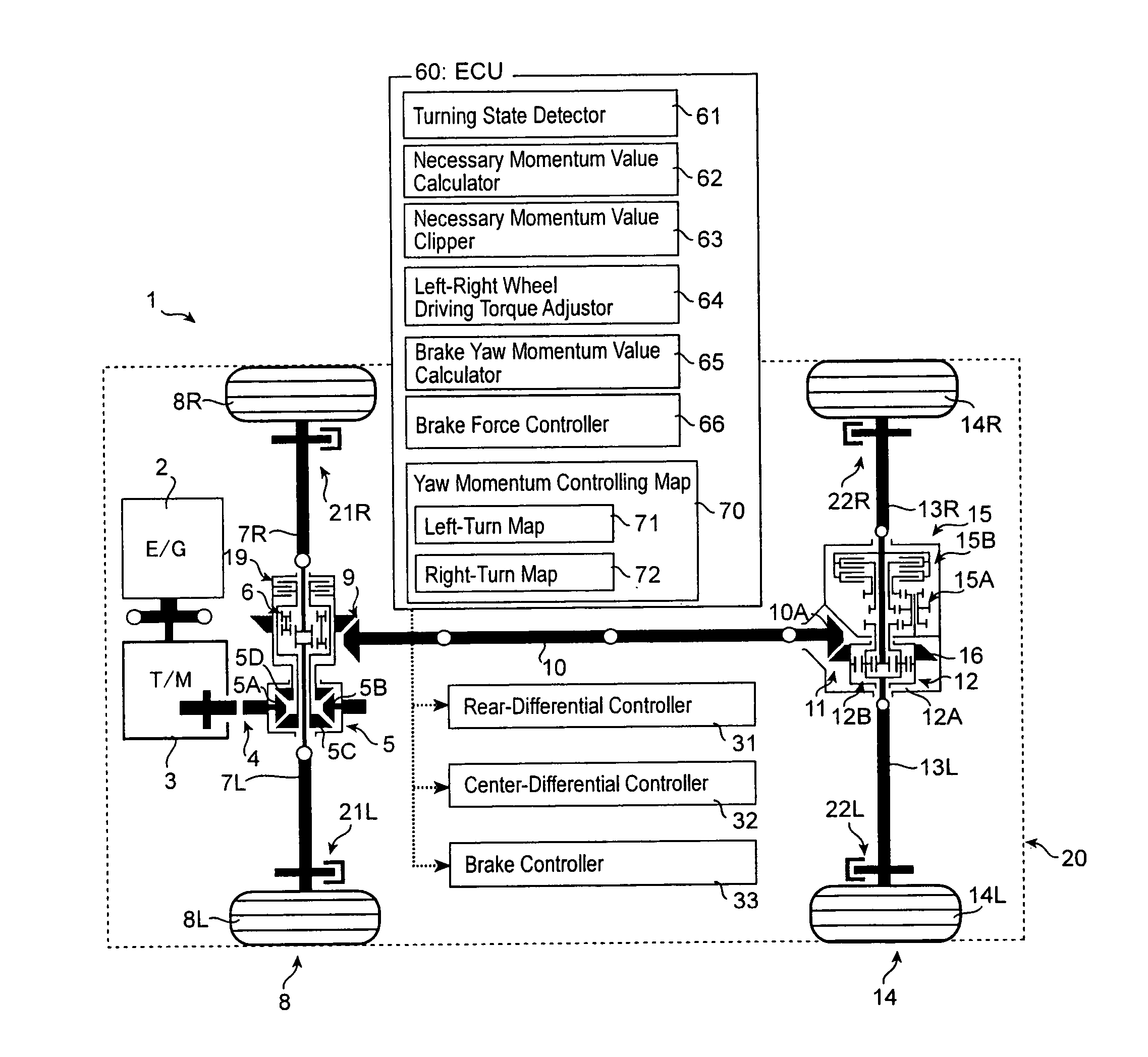
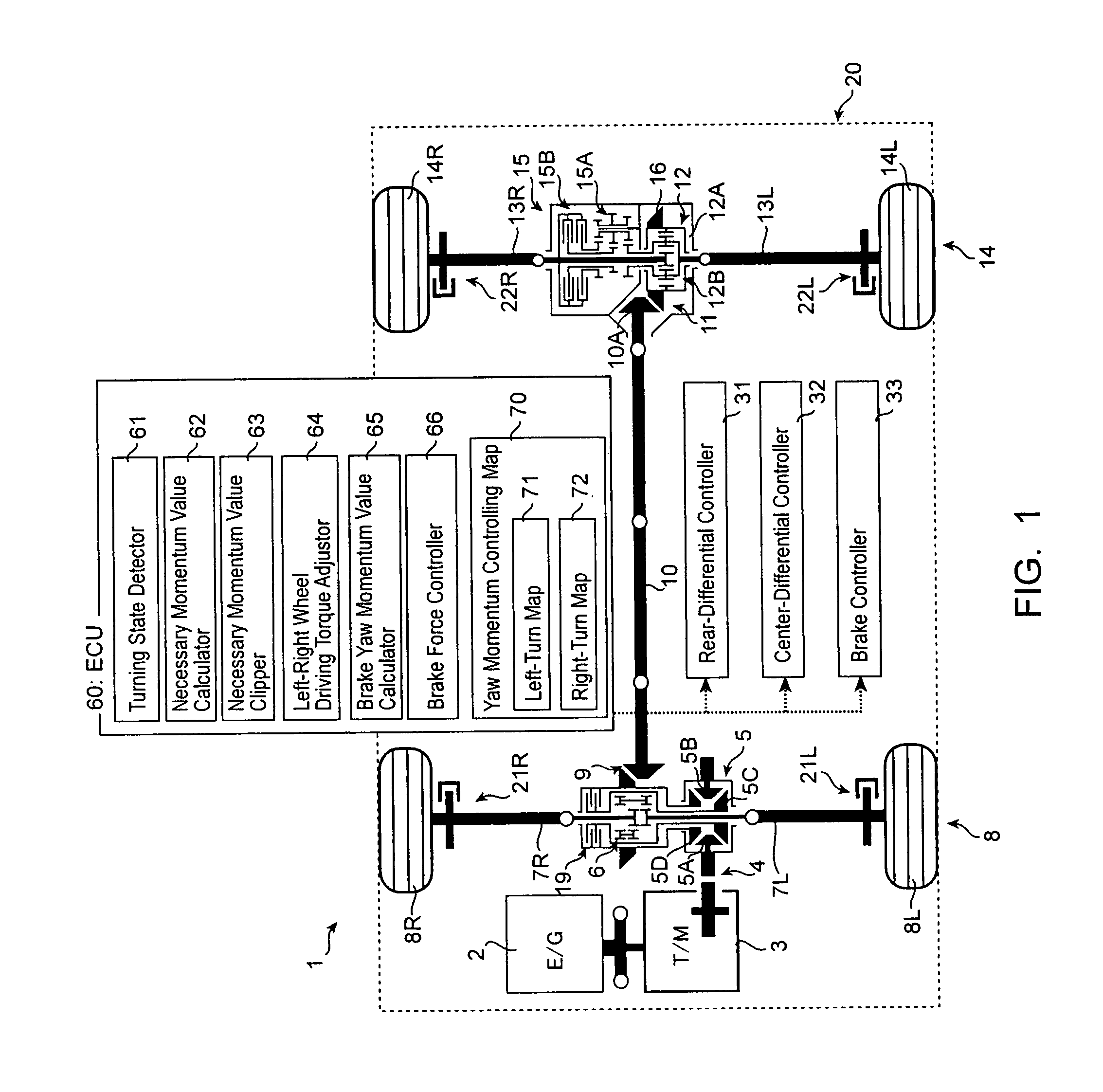
[0021] The embodiment of the present invention will now be described with reference to the accompanying drawings.

[0022] As shown in FIG. 1, an engine 2 is mounted on a vehicle 1. The torque output from the engine 2 is transmitted to a center differential 5 via transmission 3 and intermediate gear mechanism 4. The center differential 5 has a front-rear wheels limiting mechanism 19 which will be described later.

[0023] The output torque from the center differential 5 is individually transmitted to a front-right wheel 8R and a front-left wheel 8L via a front differential 6 and each of shafts 7L and 7R. The torque output from the differential 5 is individually transmitted to a rear-right wheel 14R and rear-left wheel 14L via a front-hypoid gear mechanism 9, a propeller shaft 10, a rear-hypoid gear mechanism 11, a rear-differential 12 and each of shafts 13R and 13L. The rear-differential 12 has a right-left wheel limiting mechanism 15 which will be described later.

[0024] The front-diff...


PUM


Abstract

The present invention provides a turning control apparatus for a vehicle to improve turning ability and to avoid degradation of acceleration ability. The turning control apparatus comprises: a driving torque controller (31) for adjusting driving torque between a left and right wheels (14L and 14R); means (62) for calculating a necessary yaw momentum value indicating degree of necessary yaw momentum for the turning of the vehicle; and means (63) for clipping the necessary yaw momentum value as a target yaw momentum at a maximum yaw momentum value, which is defined according to difference between the inside-wheel rotation speed and the outside-wheel rotation speed (−), if the necessary yaw momentum value is over the maximum yaw momentum value. The driving torque controller (31) adjusts between driving torque of the left and right wheels (14L and 14R) so as to generate target yaw momentum at the vehicle corresponding to the target yaw momentum value obtained by the necessary yaw momentum value clipping means (63).

Description

BACKGROUND OF THE INVENTION [0001] (1) Field of the Invention [0002] The present invention relates to a turning control apparatus for a vehicle. [0003] (2) Description of Related Art [0004] Techniques have been developed for improving safety of vehicles by achieving vehicle-stability during turning maneuvers. For example, the following related document 1 discloses generating yaw momentum of a vehicle based on the yaw-rate of the vehicle by controlling the difference in the driving torque between the left and right wheels to control the motion of the vehicle. [0005] [Related Document 1] Japanese Laid-open Publication H09-86378 [0006] However, in reality, it is difficult to generate yaw momentum at a vehicle even if the driving torque difference between the left and right wheels is varied, because the capacity of traction (adhesive friction between the wheel and the road surface) is limited. The capacity of traction is also called as gripping capacity. [0007] Particularly, to prevent ...

Claims


Application Information

Patent Timeline
Patent Type & Authority Applications(United States)
IPC IPC(8): B60T8/24B60K23/04B60T8/1755B60W10/12B60W10/16B60W10/18B60W10/184B60W30/00B60W30/02B60W30/045F16H48/10F16H48/11F16H48/36
CPCB60T8/1755B60T2201/16B60W30/02B60W10/16B60W10/184B60W10/04
Inventor MIURA, TAKAMI
Owner MITSUBISHI MOTORS CORP