

Mixed Refrigerant Liquefaction Process
- Summary
- Abstract
- Description
- Claims
- Application Information
AI Technical Summary
Benefits of technology
Problems solved by technology
Method used
Image

Examples
specific embodiments
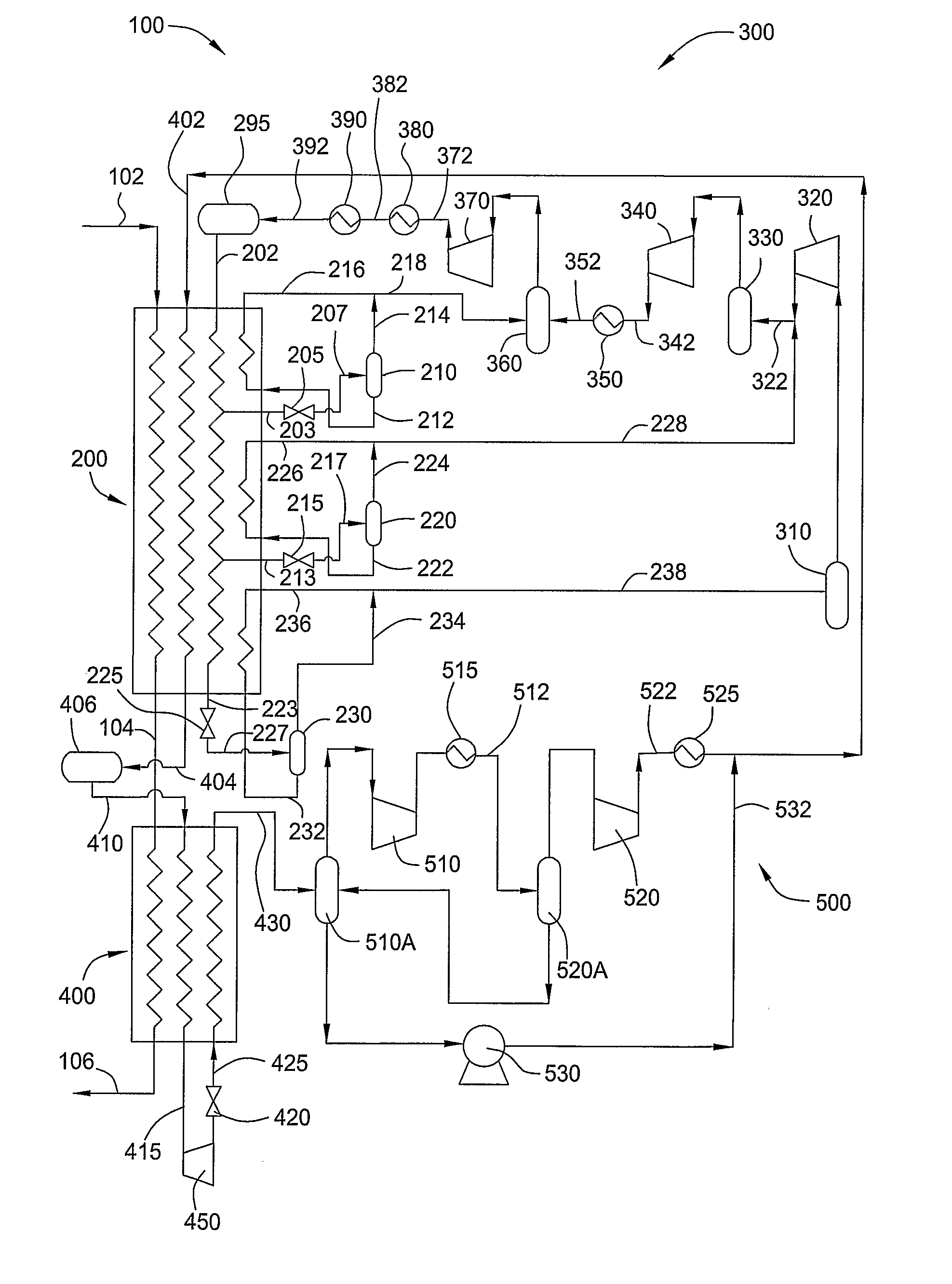
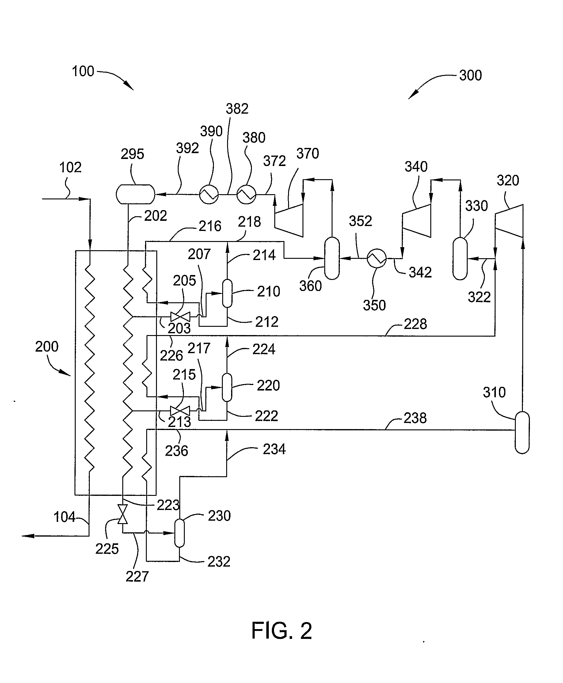
[0021] Various specific embodiments are described below, at least some of which are also recited in the claims. For example, at least one embodiment is directed to a method for liquefying a natural gas stream by placing a mixed component refrigerant in a heat exchange area with a process stream and separating the mixed component refrigerant at one or more pressure levels to produce a refrigerant vapor and a refrigerant liquid. The refrigerant vapor bypasses around the heat exchange area to a compression unit, and the refrigerant liquid passes to the heat exchange area.
[0022] At least one other specific embodiment is directed to liquefying a natural gas stream by placing a mixed component refrigerant in a heat exchange area with a process stream and withdrawing two or more side streams of the mixed component refrigerant from the heat exchange area. The side streams of mixed component refrigerant are then separated at one or more pressure levels to produce refrigerant vapors and refr...
PUM
 Abstract
Description
Claims
Application Information