Control unit of brake apparatus for vehicle

Inactive Publication Date: 2007-10-04
ADVICS CO LTD
View PDF4 Cites 11 Cited by
  • Summary
  • Abstract
  • Description
  • Claims
  • Application Information

AI Technical Summary

Benefits of technology

[0023]According to an aspect of the present invention, a control unit of a brake apparatus for a vehicle, having basic hydraulic pressure generating means generating a basic hydraulic pressure in accordance with an operation at a brake-operating member by a driver, a pump suctioning a brake fluid with the basic hydraulic pressure from a hydraulic pressure circuit in order to generate a pressurizing hydraulic pressure for generating hydraulic pressure that is higher than the basic hydraulic pressure, and a pressure difference control valve controlling an amount of pressurization relative to the basic hydraulic pressure by use of the pressurizing hydraulic pressure generated by driving the pump, wherein a hydraulic braking force is generated by applying wheel cylinder hydraulic pressure to a wheel cylinder, the wheel cylinder hydraulic pressure obtained by adding the amount of pressurization to the basic hydraulic pressure, and the control unit of the brake apparatus for the vehicle, comprises target braking force determining means determining a target value corresponding to a target braking force that is a target value of a

Problems solved by technology

In this situation, the wheel cylinder hydraulic pressure is temporally reduced; as a result, the driver may have a poor brake feeling.
When the basic hydraulic pressure hunting occurs, vibration caused by the hunting is transmitted to the brake pedal, and the driver may have poor brake feeling.

Method used


Image

  • Control unit of brake apparatus for vehicle
  • Control unit of brake apparatus for vehicle
  • Control unit of brake apparatus for vehicle

Examples


first embodiment

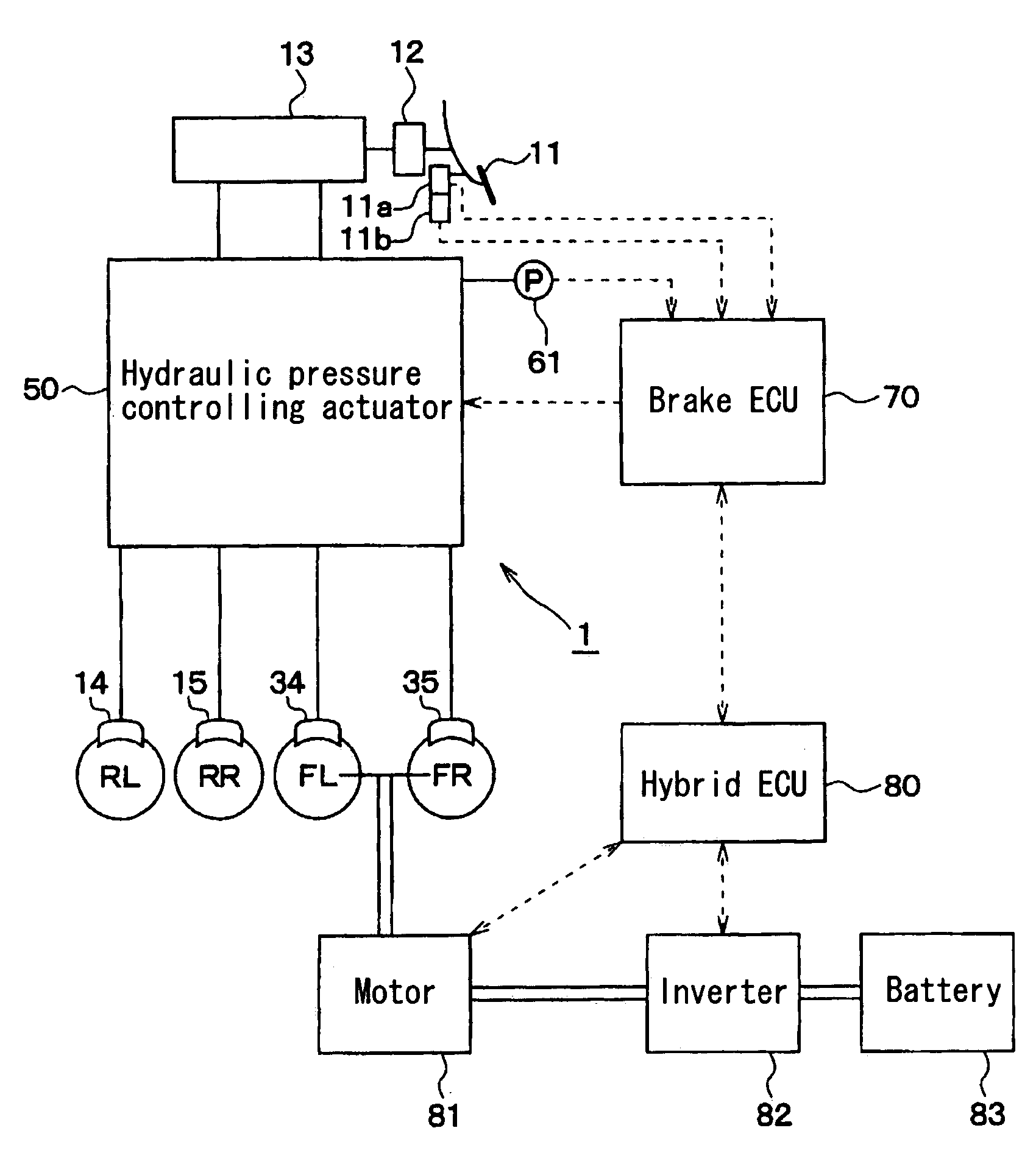
[0041]A first embodiment of the present invention will be described in accordance with the attached drawings. FIG. 1 illustrates a diagram indicating a block configuration for each function of a hybrid vehicle to which a control unit for a brake apparatus of a vehicle 1 is mounted.

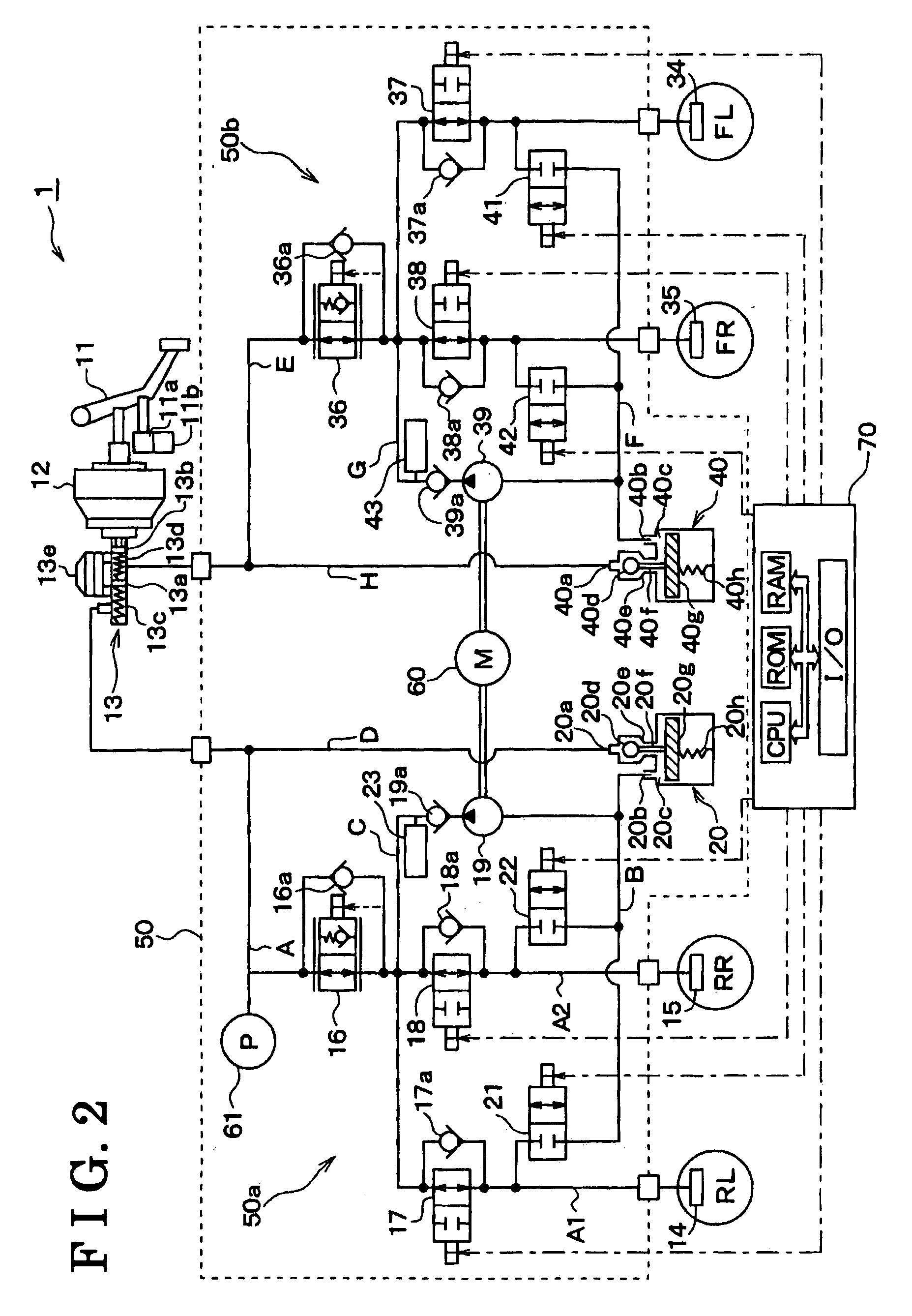
[0042]First, a hydraulic brake apparatus of the control unit for the brake apparatus of the vehicle 1 according to the embodiment will be explained. As illustrated in FIG. 1, at the control unit for the brake apparatus of the vehicle 1, a brake pedal 11, a boosting device 12, a master cylinder 13, wheel cylinders 14, 15, 34 and 35, and a hydraulic pressure controlling actuator 50 are provided so as to configure the hydraulic brake apparatus.

[0043]The control unit of the brake apparatus for the vehicle 1 further includes a brake ECU 70. The ECU 70 functions as a part of controlling means for executing a cooperative braking control operated by the regenerative brake apparatus and the hydraulic brake apparatu...

second embodiment

[0135]A second embodiment of the present invention will be explained. A control unit of the brake apparatus for the vehicle 1 in the second embodiment is similar to that in the first embodiment. Specifically, in the second embodiment, because only the configuration of the pressure difference control valve output setting process executed by the brake ECU 70 is different from that in the first embodiment, explanations of configurations of other components will be omitted.

[0136]In the first embodiment, the previous output value is set to the pressure difference output value in Step 180 indicated in the flow chart of the pressure difference control valve output setting process illustrated in FIGS. 4A and 4B, however, in the second embodiment, the pressure difference output value may be set to be greater than the previous output value as long as the pressure difference output value is lower than the previous value. In this case, same effects can be obtained.

[0137]When the pressure differ...

third embodiment

[0147](Control of Characteristic of Wheel Cylinder Hydraulic Pressure)

[0148]Described below is an outline of the control of characteristic of wheel cylinder hydraulic pressure, which is executed by the brake apparatus (the control unit of the brake apparatus for the vehicle) according to a third embodiment. Generally, there is a target characteristic (target braking force characteristic) for the characteristic of the braking force (total braking force) applied to the vehicle relative to a depression force applied to the brake pedal. Therefore, in the control unit of the brake apparatus for the vehicle, which generates braking force only by use of the hydraulic braking force, there is a target characteristic for the characteristic of the wheel cylinder pressure relative to the depression force applied to the brake pedal.

[0149]The solid line in FIG. 6 indicates the characteristic of a target value of the wheel cylinder hydraulic pressure (target wheel cylinder hydraulic pressure Pwt) ...


PUM


Abstract

A control unit of a brake apparatus for a vehicle comprises target braking force determining means determining a target value corresponding to a target braking force that is a target value of a braking force on the basis of a basic value corresponding to the basic hydraulic pressure, compensation braking force controlling means controlling a compensation braking force so that a total value corresponding to a total braking force is equal to the target value corresponding to the target braking force, and the target braking force determining means including hunting reducing hydraulic pressure calculating means calculating a controlling value corresponding to a hunting reducing hydraulic pressure, the controlling value obtained by applying process to the basic hydraulic pressure in order to control a variation thereof, and the target value corresponding to the target braking force is determined by use of the controlling value corresponding to the hunting reducing hydraulic pressure.

Description

CROSS REFERENCE TO RELATED APPLICATIONS[0001]This application is based on and claims priority under 35 U.S.C. § 119 to Japanese Patent Application 2006-102236 filed on Apr. 3, 2006 and Japanese Patent Application 2006-107284 filed on Apr. 10, 2006, the entire content of which is incorporated herein by reference.FIELD OF THE INVENTION[0002]The present invention relates to a control unit of a brake apparatus for a vehicle generating a braking force by means of a cooperative braking control operated by a hydraulic brake apparatus generating a hydraulic braking force using brake fluid together with a regenerative brake apparatus generating a regenerative braking force using a motor, a generator or the like.BACKGROUND[0003]A control unit of the brake apparatus for the vehicle disclosed in JP2006-21745A generates a braking force corresponding to a target braking force by means of a cooperative braking control operated using a hydraulic braking force generated by a hydraulic brake apparatu...

Claims


Application Information

Patent Timeline
IPC IPC(8): B60T13/74
CPCB60T1/10
Inventor KOKUBO, KOICHIMAKI, KAZUYANAITO, MASAYUKI
Owner ADVICS CO LTD
Why Eureka
Try Eureka