
Reverse current preventing circuit with an automatic correction of reference

a reverse current and reference technology, applied in the direction of electric variable regulation, process and machine control, instruments, etc., can solve the problems of inability to compensate the delay by using a fixed offset current, and inability to accurately prevent the occurrence of reverse currents.

Active Publication Date: 2007-10-11
GLOBAL MIXED MODE TECH
View PDF13 Cites 26 Cited by
  • Summary
  • Abstract
  • Description
  • Claims
  • Application Information

AI Technical Summary

Benefits of technology

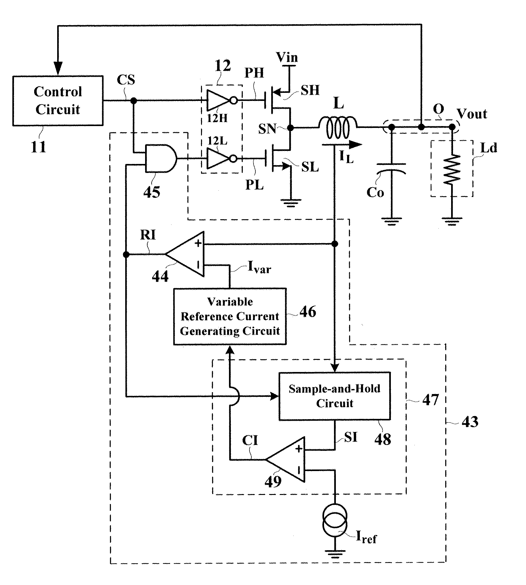
[0013] In view of the above-mentioned problems, an object of the present invention is to provide a reverse current preventing circuit, which is applied in a synchronous switching voltage converter, with an automatic correction of reference so as to accurately prevent the occurrence of the reverse current.

Problems solved by technology

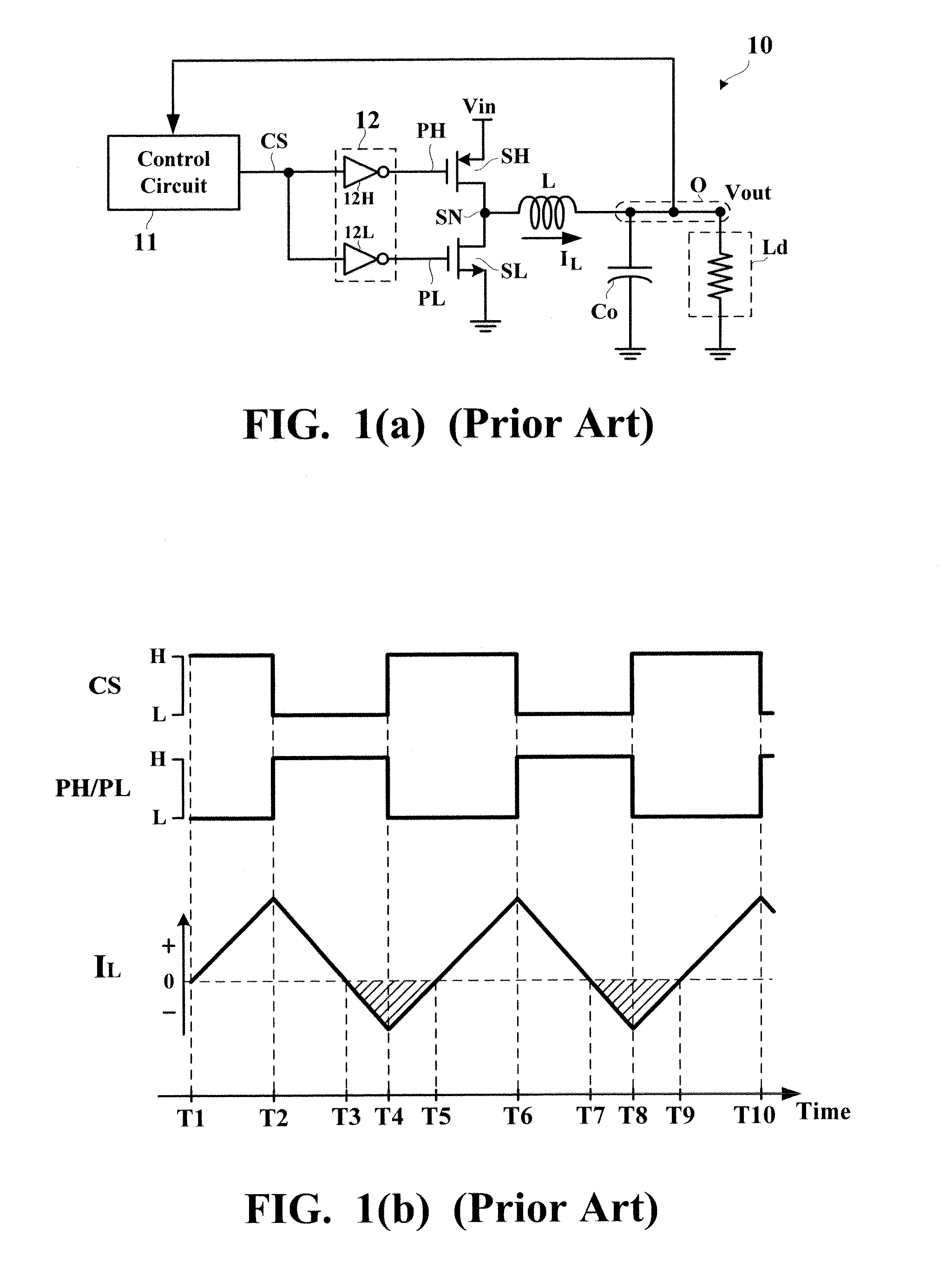
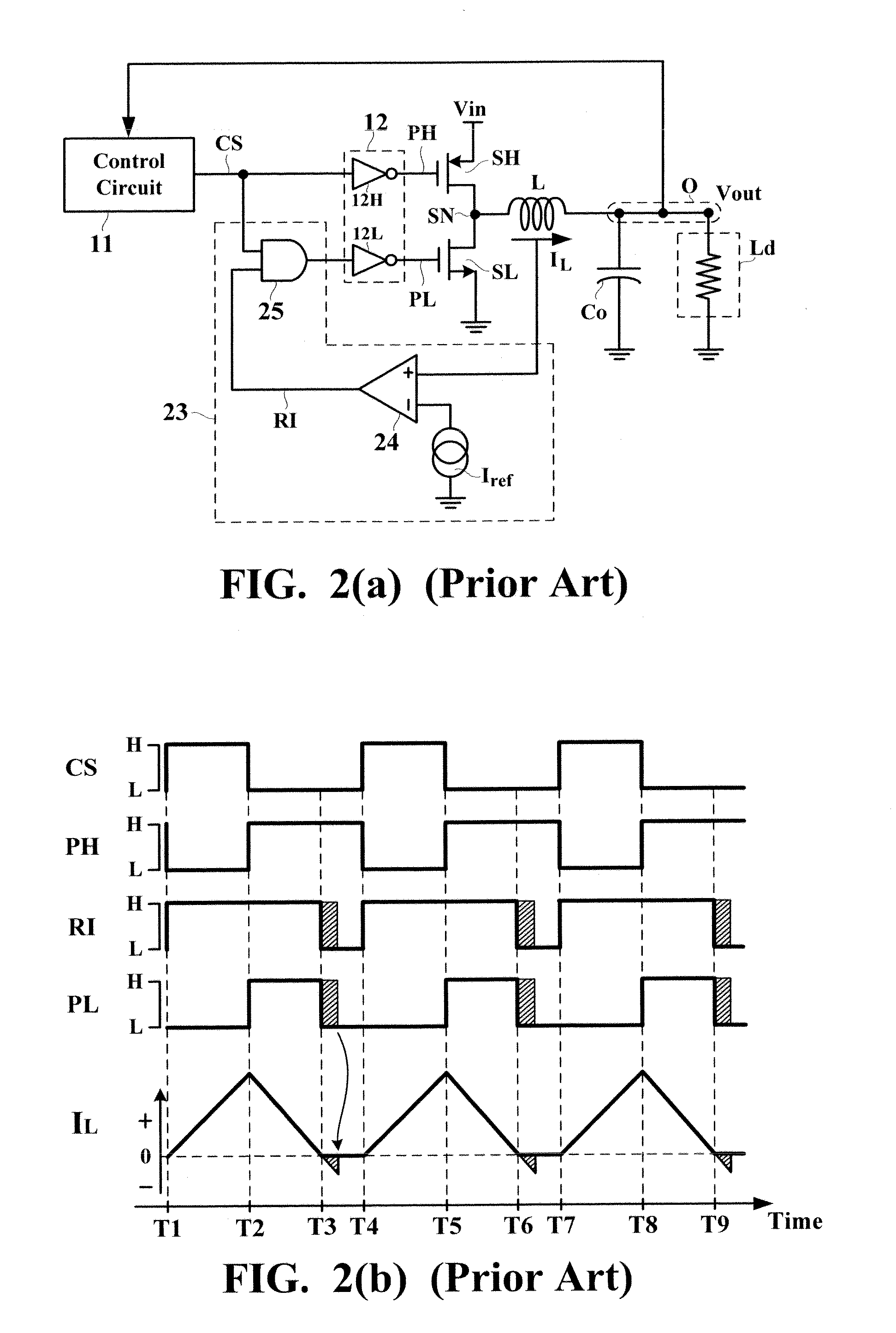
In other words, the reversal of the inductor current IL will inevitably occur during such delay.
As a result, the delay caused by the current comparing circuit 24 is not a constant and therefore it is impossible to compensate the delay by using a fixed offset current.
In other words, the reversal of the inductor current IL will inevitably occur during such delay.
As a result, the delay caused by the voltage comparing circuit 34 is not a constant and therefore it is impossible to compensate the delay by using a fixed offset voltage.

Method used


Image

  • Reverse current preventing circuit with an automatic correction of reference
  • Reverse current preventing circuit with an automatic correction of reference
  • Reverse current preventing circuit with an automatic correction of reference

Examples


Embodiment Construction

[0027] The preferred embodiments according to the present invention will be described in detail with reference to the drawings.

[0028]FIG. 4 is a circuit diagram showing a reverse current preventing circuit 43 according to a first example of the present invention. Referring to FIG. 4, the reverse current preventing circuit 43 has a current comparing circuit 44, an AND logical gate 45, a variable reference current generating circuit 46, a current correcting circuit 47, and a fixed reference current source Iref. The current comparing circuit 44 has a non-inverting input terminal for receiving the inductor current IL, and an inverting terminal for receiving a variable reference current signal Ivar output from the variable reference current generating circuit 46. The AND logical gate 45 has a first input terminal for receiving the switch control signal CS, and a second input terminal for receiving the preventing signal RI output from the current comparing circuit 44. The output terminal...


PUM


Abstract

A synchronous switching voltage converter has a first switch, a second switch, and an inductor, coupled together to a switch node. A reverse current preventing circuit has a fixed reference current source, a correcting circuit, a variable reference current generating circuit, and a comparing circuit. Based on a comparison between an inductor current and the fixed reference current source, the correcting circuit generates a correcting signal. The variable reference current generating circuit generates a variable reference current signal, which is adjusted in accordance with the correcting signal. Based on a comparison between the inductor current and the variable reference current signal, the comparing circuit applies a preventing signal to the second switch so as to turn off the second switch.

Description

BACKGROUND OF THE INVENTION [0001] 1. Field of the Invention [0002] The present invention relates to a reverse current preventing circuit and, more particularly, to a reverse current preventing circuit, which is applied in a synchronous switching voltage converter, with an automatic correction of reference so as to accurately prevent occurrence of current reversal. [0003] 2. Description of the Related Art [0004]FIG. 1(a) is a circuit diagram showing a conventional synchronous switching voltage converter 10. The synchronous switching voltage converter 10 converts an input voltage source Vin into a regulated output voltage Vout for being supplied to a load Ld. A high-side switch SH is coupled between the input voltage source Vin and a switch node SN, while a low-side switch SL is coupled between the switch node SN and a ground potential. In the example shown in FIG. 1(a), the high-side switch SH is implemented by a PMOS transistor while the low-side switch SL is implemented by an NMOS...

Claims


Application Information

Patent Timeline
Patent Type & Authority Applications(United States)
IPC IPC(8): H02H7/122
CPCH02H7/1213H02M1/32Y02B70/1466H02M2001/0025H02M3/1588Y02B70/10H02M1/0025
Inventor CHEN, YUNG-CHIH
Owner GLOBAL MIXED MODE TECH
Learn More