Dental implant

Inactive Publication Date: 2007-11-01
PERIOSEAL
View PDF15 Cites 31 Cited by
  • Summary
  • Abstract
  • Description
  • Claims
  • Application Information

AI Technical Summary

Benefits of technology

[0021]In a further embodiment, the implant proximal segment may have a generally circumferential or annular concave cross-section such that the crown distal end can be provided with a complementary rounded or blunt circumferential edge instead of a less desirable circumferential knife edge configuration. The rounded shape of the crown distal end provides increased surface to more uniformly distribute occlusal forces applied to the joint.
[0022]As was mentioned above, such occlusal forces are typically the result of m

Problems solved by technology

Over time, such bone loss can compromise the integrity of the implant or cause its failure by breaking loose from the bony structure into which the implant is embedded.
Obviously, such failure, in addition to providing inconvenience and discomfort for the patient, is of serious medical concern due to the resulting bone loss or mutilation potent

Method used


Image

  • Dental implant
  • Dental implant
  • Dental implant

Examples


Embodiment Construction

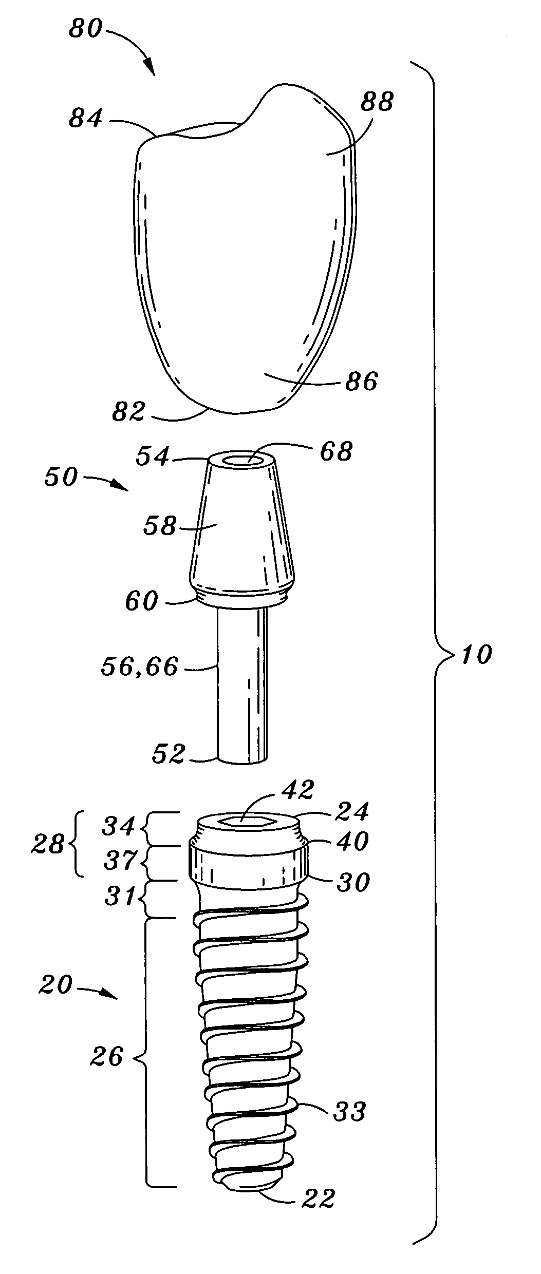
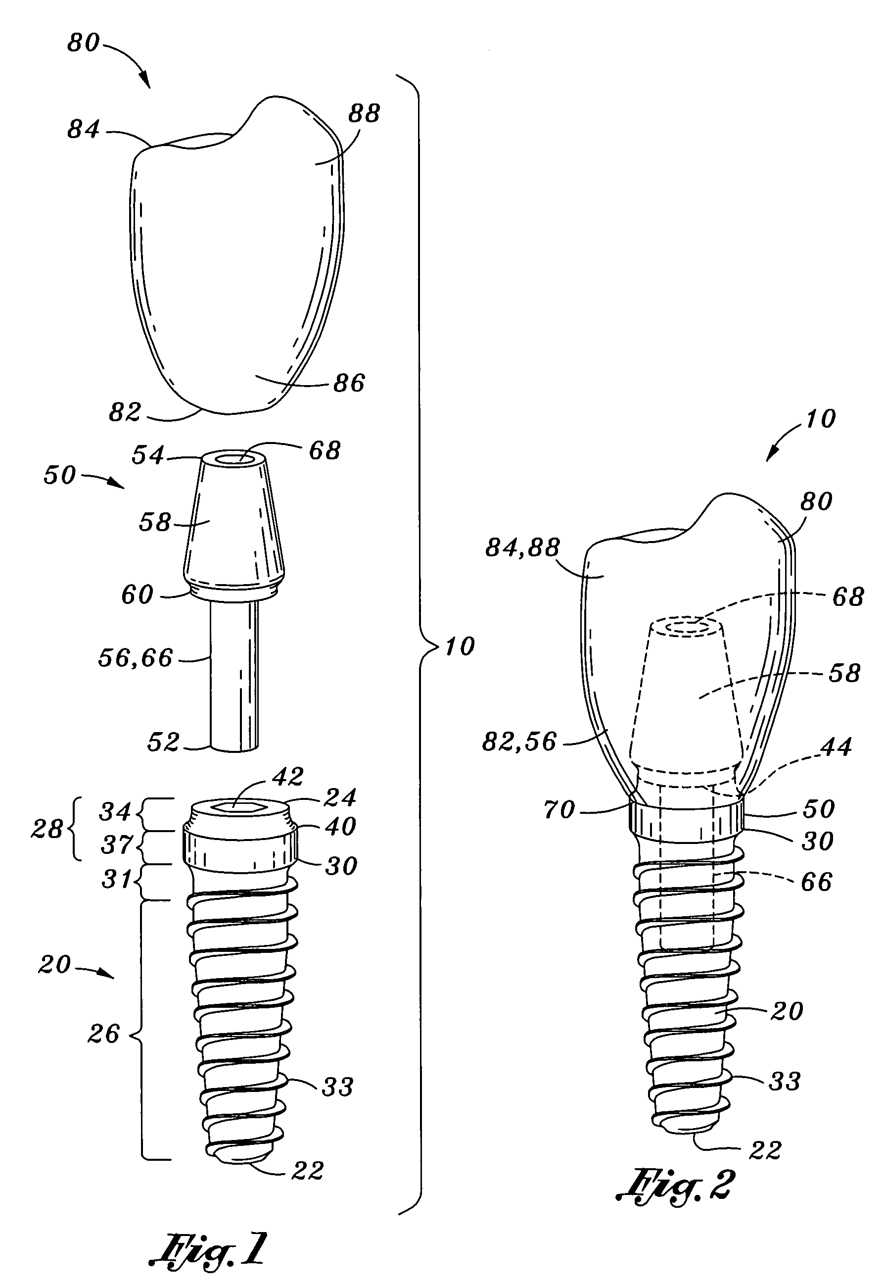
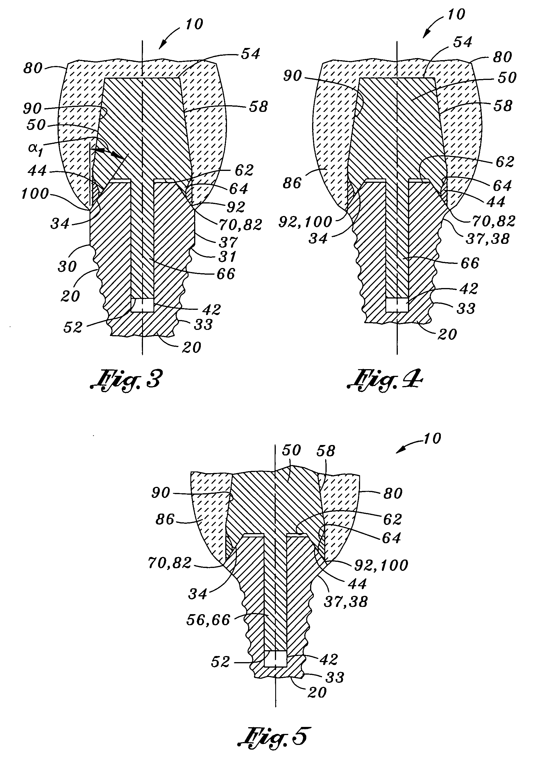
[0040]Referring now to the drawings wherein the showings are for purposes of illustrating various embodiments of the present invention only and not for purposes of limiting the same, FIGS. 1-11 depict a dental prosthesis 10 which, in its broadest sense, comprises an implant 20, an abutment 50 and a crown 80. The implant 20 is adapted to be embedded into the bony structure of a patient's mouth or oral cavity. The implant 20 itself includes an elongate implant distal portion 26 which defines an implant distal end 22. The implant distal portion 26 may be further divided into an implant body 32 and an implant trunk 31. The implant distal portion 26 may further include external threads 33 formed on the implant body 32 which are preferably configured to be threadably engaged to the bony structure.

[0041]The implant 20 may further include an implant neck or implant proximal portion 28. As can be seen in the figures, the implant proximal portion 28 is separated from the implant trunk 31 by a...


PUM


Abstract

A dental prosthesis comprises an implant, an abutment and a crown. The implant has distal and proximal portions with the implant proximal portion including distal and proximal segments. The implant proximal segment has an outer surface. The abutment has distal and proximal segments and defines an abutment shoulder therebetween. The abutment shoulder is configured to circumferentially engage the outer surface of the implant proximal segment such that an implant abutment joint is defined therebetween. The crown is configured to be positioned over the abutment and the implant such that the crown covers the implant abutment joint. The implant proximal segment has an annular concave cross-section such that the crown distal end has a rounded shape to reduce the potential for stress cracking of the crown.

Description

CROSS-REFERENCE TO RELATED APPLICATIONS[0001]This application claims priority to U.S. Provisional Application Ser. No. 60 / 795,876, filed on Apr. 28, 2006 and entitled DENTAL IMPLANT, the entire contents of which is expressly incorporated by reference herein.STATEMENT RE: FEDERALLY SPONSORED RESEARCH / DEVELOPMENT[0002](Not Applicable)BACKGROUND[0003]The present invention relates generally to dental prostheses and, more particularly, to a dental prosthesis including an implant, an abutment which is attachable to the implant, and a crown which is attachable to the abutment and the implant such that the joint defined between the abutment and the implant is covered and effectively sealed.[0004]As is well known in the art, dental prostheses are commonly used in the dental field to address extensive damage to teeth caused by injury or disease. A typical dental prosthesis comprises an implant, an abutment and a crown. The implant itself generally comprises a metallic component which is impla...

Claims


Application Information

Patent Timeline
IPC IPC(8): A61C8/00
CPCA61C8/0048A61C8/006A61C8/0054A61C8/005
Inventor CALLAN, DONALD P.
Owner PERIOSEAL
Why Eureka
Try Eureka