Method for Correcting Measured Image Values

Active Publication Date: 2007-11-08
X RITE SWITZERLAND
View PDF5 Cites 14 Cited by
  • Summary
  • Abstract
  • Description
  • Claims
  • Application Information

AI Technical Summary

Benefits of technology

[0015] An objective of this invention is to propose a solution to these known problems and enable a simple image measuring method or any color measuring system

Problems solved by technology

Colorimetric calibration alone is not sufficient for the application of imaging technology in the printing industry.
One known problem is the wet-dry problem which primarily causes difficulties with regard to the measuring technology used in the offset printing method.
During the drying process, the color coating conforms to the structure of the substrate surface, which reduces the sheen and causes significant changes in the measurement values over time (during the drying phase), especially in the case of mat papers.
To date, the polarization filter measuring method has not been used in image-producing color measuring systems for controlling printing processes.
The reason for this is that process control systems must be able to take measurements quickly and the orthogonal polarization filters cause a light loss based on a factor of 8 to 10, which has to be compensated by correspondingly longer measuring times, which would be too long for controlling the printing processes.
However, the quality obtained on the basis of the correction is not satisfactory.
The accuracy of the correction is limited by the large number of different printing substrates with different surface properties.
The limited set of typical paper qualities

Method used


Image

  • Method for Correcting Measured Image Values
  • Method for Correcting Measured Image Values
  • Method for Correcting Measured Image Values

Examples


Embodiment Construction

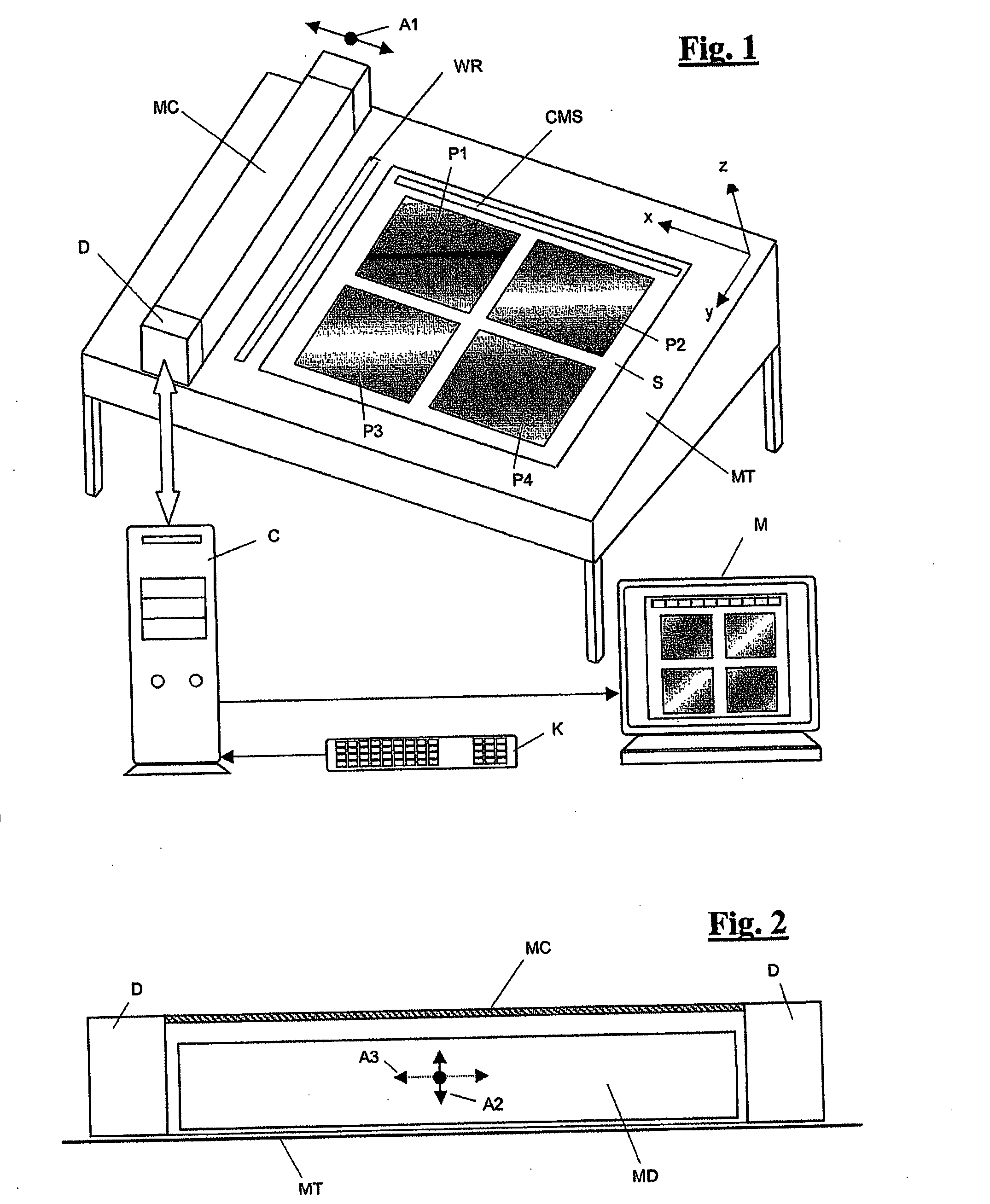
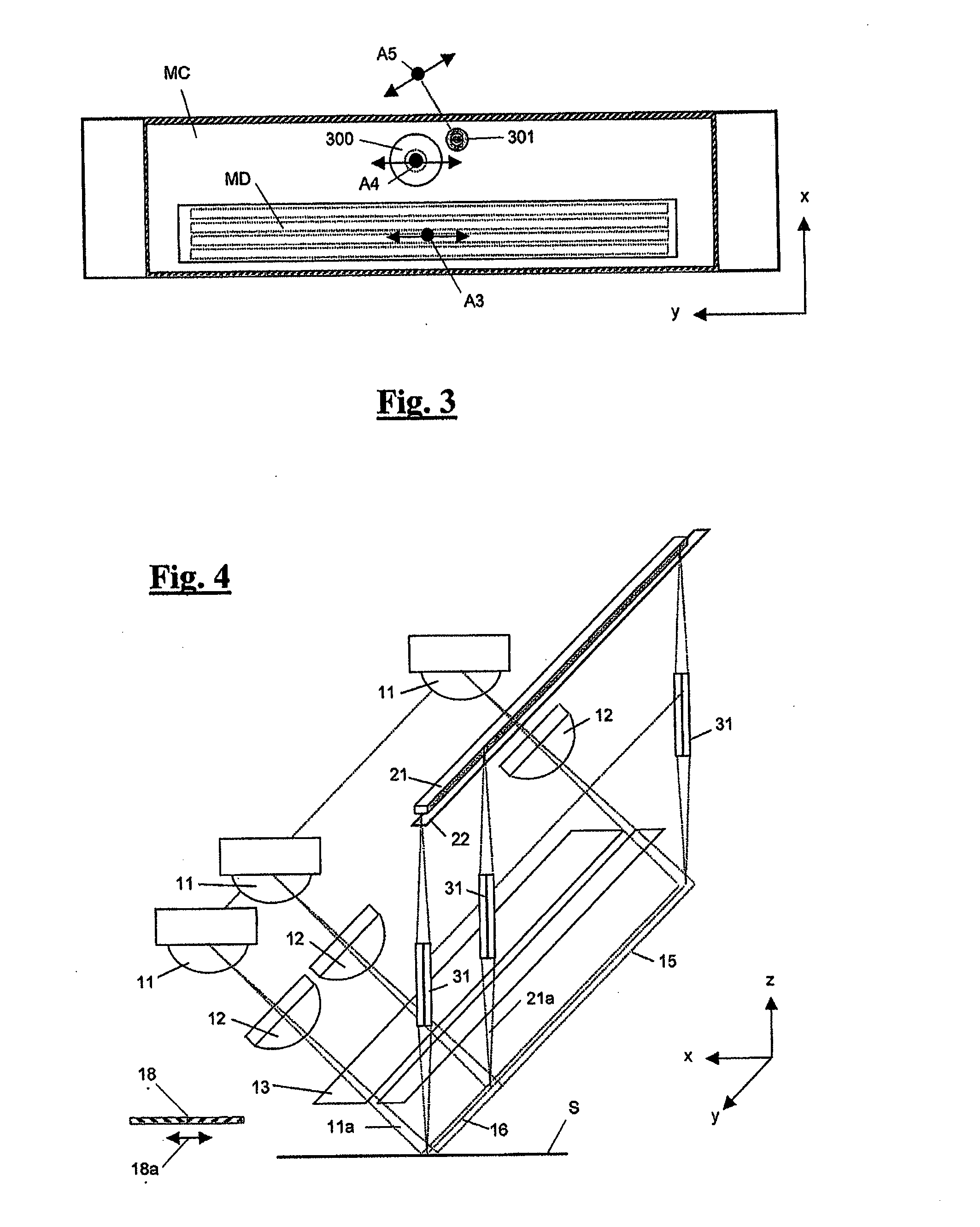
[0028]FIGS. 1-4 illustrate a preferred embodiment of the scanning device. In terms of its general construction, it corresponds to standard measuring apparatus, of the type typically used in the graphics industry for photoelectrically measuring printed sheets during a printing process on the basis of pixels, for example. Such printed sheets are also be referred to as measurement object or sample in the following description.

[0029] The scanning device comprises a sub-structure in the form of a measuring table MT with a usually inclined rectangular surface on which the measurement object S—the printed sheet to be measured—can be positioned. The printed sheet S typically contains various (in this example four) graphic illustrations P1-P4 and a (or several) color measuring strip CMS. In order to position the measurement object S, stops are provided on the measuring table MT, although these are not illustrated. The measurement object S is preferably secured on the measuring table MT by e...


PUM


Abstract

Image measurement values of a measurement object, in particular a printed sheet, measured by means of a photoelectric image measuring unit operating on the basis of pixels are corrected with respect to at least one influencing variable which influences the measurement result with a view to at least partially eliminating the effect of this influencing variable on the measuring process. The image measurement values measured by the image measuring unit are converted by correction parameters of a parameter-based correction model into corrected image measurement values which no longer contain the influencing variable affecting the measuring process. The correction parameters used for the parameter-based correction model are automatically calculated using reference measurement values measured at reference measurements points on preferably the same measurement object by means of a reference measuring unit and the image measuring unit. In particular, image measurement values measured without polarization filters are converted into polarization filter image measurement values by means of this method. Influences induced by print medium, fluorescence effects and the influences of non-standard measuring geometries are also corrected.

Description

FIELD OF THE INVENTION [0001] The invention relates to a method of correcting image measurement values of a measurement object obtained by means of a photoelectrically operating image measuring system on the basis of image pixels, in particular a printed sheet. BACKGROUND ART [0002] These days, color and density measurement values of printed sheets are often detected by means of a multi-channel measuring method operated in parallel. A multi-channel, measuring method operated in parallel is referred to as an image measuring technique below because it is typically used to detect the measurement data of a whole image or a section of an image on the basis of image pixels. With the age of digital processing, ever increasing importance is being ascribed to the availability of image measurement values and the direct use of digital data from the preliminary processing stage for controlling printing machines. Image measurement values permit efficient quality control of the printed product an...

Claims


Application Information

Patent Timeline
IPC IPC(8): G06F19/00
CPCG01J3/02G01J3/0224G01J3/50G01J3/51H04N1/02815G01J2003/468G01N21/27G01N21/274G01J3/513
Inventor EHBETS, PETERKOHLBRENNER, ADRIANAMMETER, HARALD
Owner X RITE SWITZERLAND
Why Eureka
Try Eureka