Firing stand for shaped charges

a technology of firing stand and charge, which is applied in the direction of explosive charges, fluid removal, borehole/well accessories, etc., can solve the problems of difficult to achieve precision, significant burden on the precise deployment of firing stand of disruptor systems,

Active Publication Date: 2020-12-24
THE SEC OF STATE FOR DEFENCE IN HER BRITANNIC MAJESTYS GOVERNMENT OF THE UK OF GREAT BRITAIN & NORTHERN IRELAND
View PDF0 Cites 0 Cited by
  • Summary
  • Abstract
  • Description
  • Claims
  • Application Information

AI Technical Summary

Benefits of technology

[0016]The firing stand provides the benefit of dual use as both a stand for firing shaped charges, but also as part of the transport solution for the shaped charges. In preferred embodiments of the invention the firing stand is substantially formed from an ammunition packaging material. The term ‘substantially formed’ is used to acknowledge that minor elements of the firing stand, such as the rods used for connecting the mounting panels in some embodiments of the invention, may not be formed from ammunition packaging material. By forming the firing stand from ammunition packaging material, the firing stand in the transport configuration provides the necessary packaging material for transporting shaped charges themselves. This means the firing stand with shaped charges mounted therein, can be placed inside an ammunition container and transported without requiring a significant amount of additional ammunition packaging material. Indeed forming a firing stand from ammunition packaging material may be beneficial even for firing stands for single shaped charges. Furthermore, at a deployment location, the shaped charges can be removed from the ammunition container already in their firing stand. Further preferred embodiments of the invention use low density plastazoate foam as the packaging material. Using low density foam of this type reduces the hazard posed by fragmentation of the firing stand during use of the shaped charges. Furthermore, low density plastazoate foam is a relatively lightweight ammunition packaging material to transport to and from a deployment location.
[0017]According to a second aspect of the invention there is provided a

Problems solved by technology

This places significant burden on the precise deployment of the firing stand of the disruptor system, such that the shaped charge is orientated towards the optimum location on the target e

Method used


Image

  • Firing stand for shaped charges
  • Firing stand for shaped charges
  • Firing stand for shaped charges

Examples


Embodiment Construction

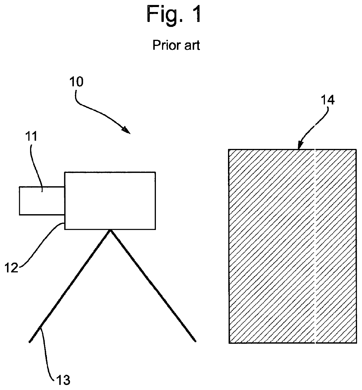
[0028]FIG. 1 shows an illustration of a prior art disruptor system 10 being aimed towards an improvised explosive device 14. The prior art disruptor system comprises a single shaped charge 12, detonator 11 and a firing stand 13. The firing stand 13 is for illustrative purposes only and practically may comprise more legs supporting shaped charge 12. The shaped charge 12 is orientated towards explosive device 14 such that when detonator 11 detonates shaped charge 12, the shaped charge jet (not shown) propagates towards explosive device 14. The shaped charge jet subsequently penetrates explosive device 14 and damages internal components so as to prevent detonation of device 14. This illustration shows the capability of the prior art to only fire a single shaped charge 12. The single shaped charge 12 delivering a disruptive effect to explosive device 14 along the direction of penetration of the respective shaped charge jet. For explosive devices 14 wherein the internal contents, or the ...


PUM


Abstract

A firing stand (30) for mounting a plurality of shaped charges. The firing stand (30) can be configured by a user between a transport configuration in which shaped charges are stored for transport, and at least a first firing configuration from which shaped charges can be deployed. Inter-connected rotating panels (31) may be used to provide user configurability to the firing stand (30), with shaped charges optionally being mounted in panel apertures (36). The firing stand provides for rapid and configurable deployment of multiple shaped charges.

Description

TECHNICAL FIELD OF THE INVENTION[0001]This invention relates to the field of firing stands, in particular to firing stands suitable for mounting shaped charges.BACKGROUND TO THE INVENTION[0002]Shaped charges are used in a variety of applications to penetrate into, breach, or cut, a target object or material. Exemplar applications include oil well perforation, the breaching of barriers such as doors, windows or walls, and military applications such as armour penetration or the disruption of improvised explosive devices. A shaped charge comprises an outer casing having an internal cavity filled with explosive material, the explosive material having a void or hollow cut into one end that is then lined with a metallic shaped charge liner. Upon detonation of the explosive, the presence of the void or hollow results in a focussing effect of the detonation onto the shaped charge liner. The liner resultantly collapsing to form a jet of fast moving metallic material propagating axially away ...

Claims


Application Information

Patent Timeline
IPC IPC(8): E21B43/117F42B1/028
CPCE21B43/119F42B1/028F42D3/00F42B1/032E21B43/117F42B1/02F42D5/04
Inventor NEWELL, DAVID TIMOTHY
Owner THE SEC OF STATE FOR DEFENCE IN HER BRITANNIC MAJESTYS GOVERNMENT OF THE UK OF GREAT BRITAIN & NORTHERN IRELAND
Why Eureka
Try Eureka