Nuclear Magnetic resonance probe coil
a nuclear magnetic resonance and coil technology, applied in the direction of magnetic measurement, instruments, measurement devices, etc., can solve the problems of limited volume of static magnetic field interacting with a superconductor, limited disorder of static magnetic field caused by a large magnetic susceptibility of the superconductor, and no consideration is taken into a method of strengthening coupling and improving signal intensity, so as to facilitate the measurement of multiple nuclear species
- Summary
- Abstract
- Description
- Claims
- Application Information
AI Technical Summary
Benefits of technology
Problems solved by technology
Method used
Image
Examples
first embodiment
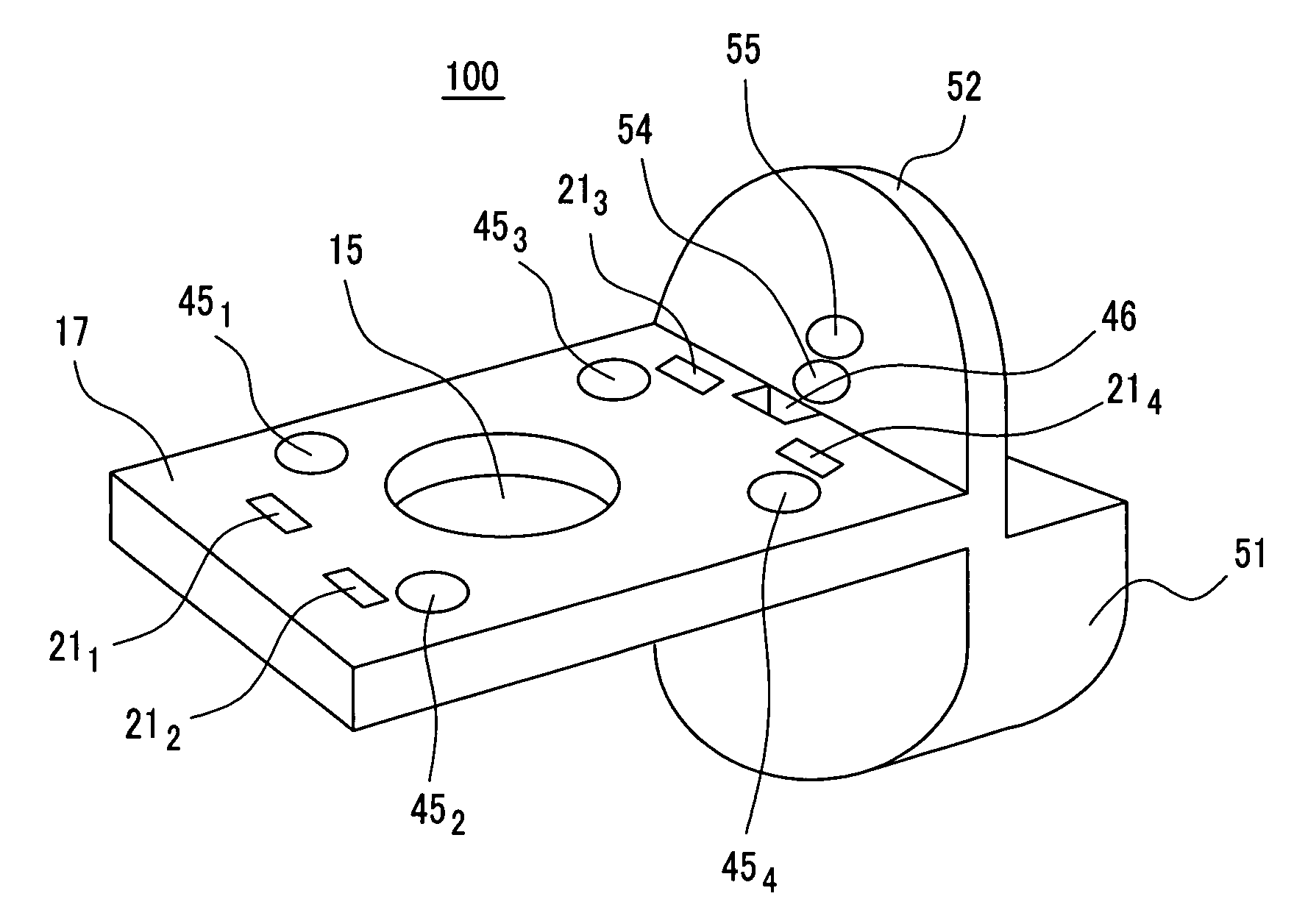
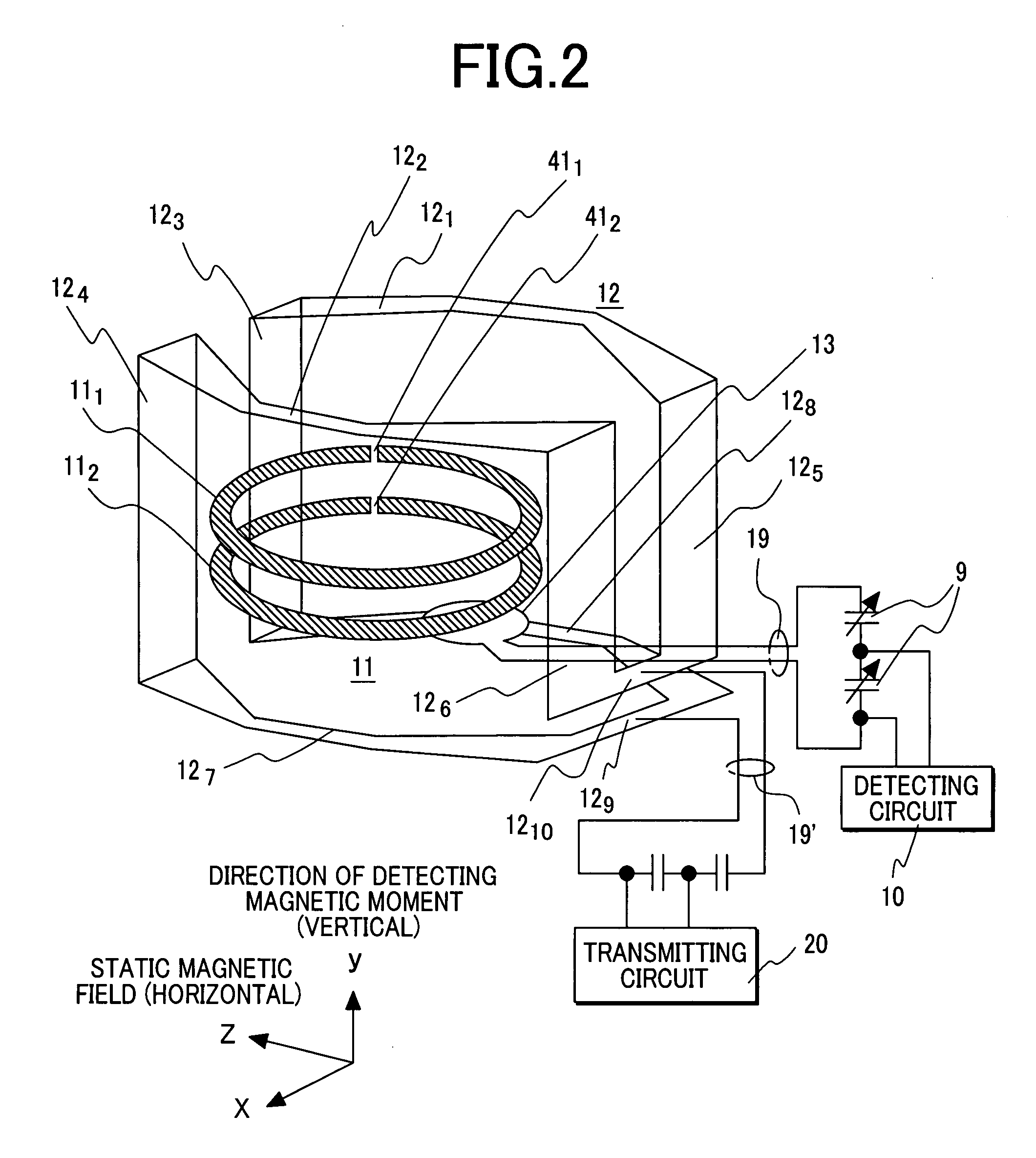
[0024]The first embodiment employs a probe, to which a static magnetic field is horizontally applied and which is horizontally extended in the form of a bar, for the purpose of realizing a high-sensitivity nuclear magnetic resonance apparatus. The probe has a reception coil, which is composed of superconducting thin-film rings, disposed in the distal part thereof. The first embodiment relates to the structure of a probe coil.
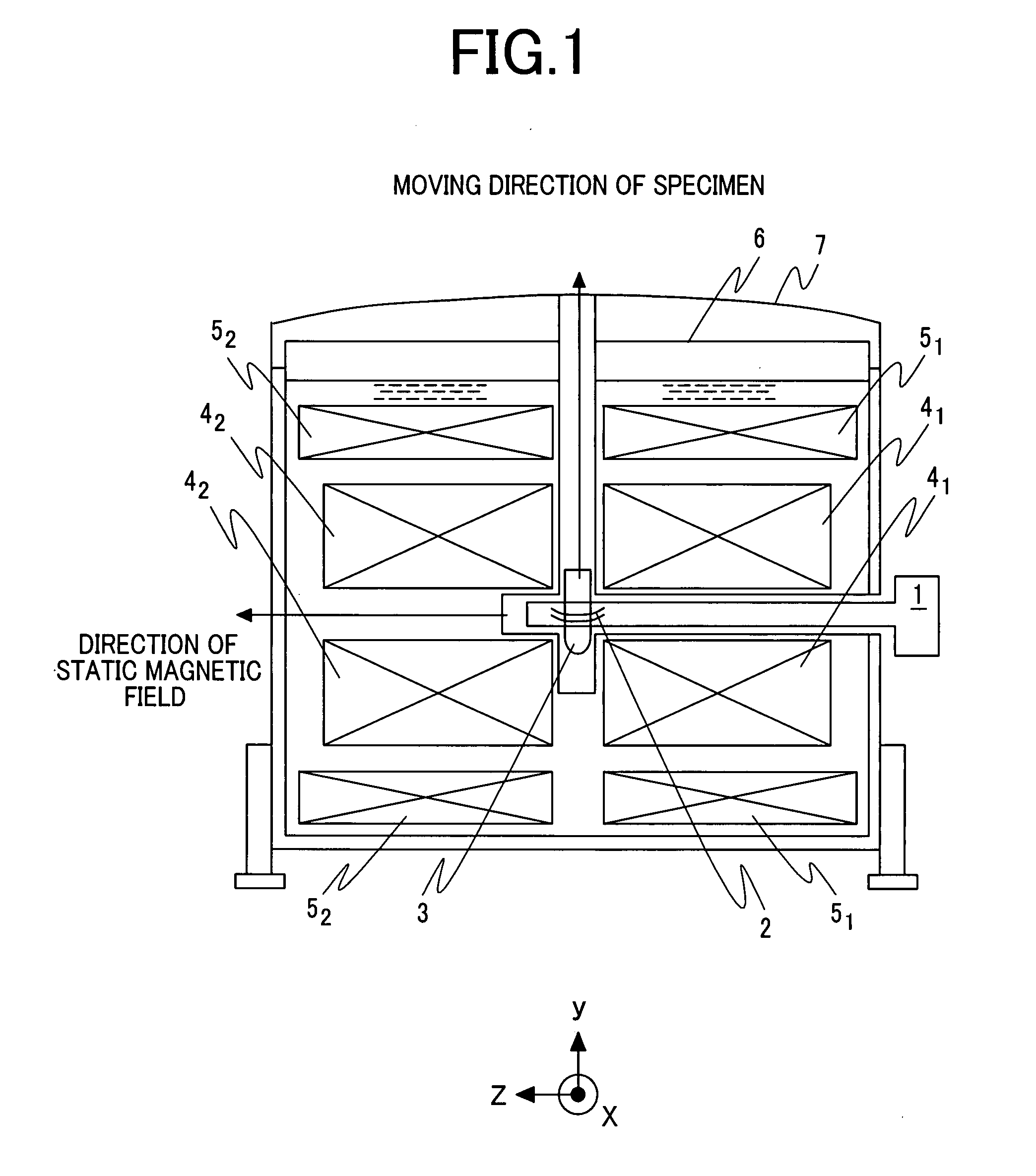
[0025]FIG. 1 is a sectional view showing the overall configuration of a nuclear magnetic resonance apparatus including a probe coil in accordance with the first embodiment. Reference numerals 41 and 42 denote solenoid coils that are produced by bisecting a coil and used to apply a static magnetic field and that are placed sideways. Reference numerals 51 and 52 denote solenoid coils that are produced by bisecting a coil and disposed on the peripheries of the solenoid coils 41 and 42 respectively for the purpose of correcting a magnetic field. The coils are mounte...
second embodiment
[0046]Next, the second embodiment of the present invention will be described below. The overall configuration of a nuclear magnetic resonance apparatus in accordance with the second embodiment is identical to that of the nuclear magnetic resonance apparatus in accordance with the first embodiment including the probe coil shown in FIG. 3 except a point that the structure of a reception coil is different from that of the reception coil 11 shown in FIG. 3 and employed in the first embodiment. FIG. 5A and 5B are a side view and a plan view respectively which illustratively show the structure of a probe coil 2 in accordance with the second embodiment. However, for a better understanding, the plan view shows the structure with a sapphire substrate 261, on which a superconducting thin-film ring 111 is formed, and sapphire substrates 263 and 265, which are located above the sapphire substrate 261, excluded therefrom.
[0047]As readily seen from the comparison of FIG. 5 with FIG. 3, although t...
third embodiment
[0050]Next, the third embodiment of the present invention will be described below. The overall structure of a nuclear magnetic resonance apparatus in accordance with the third embodiment is identical to that of the nuclear magnetic resonance apparatus in accordance with the first embodiment including the probe coil shown in FIG. 3. The third embodiment is different from the first embodiment in a point that a probe coil 2 is designed to measure two nuclear species. FIG. 6A and FIG. 6B are a side view and a plan view respectively which illustratively shows the structure of the probe coil 2. For a better understanding, the plan view shows the structure with sapphire substrates, on which respective superconducting thin-film rings 11 are formed, ignored.
[0051]As readily seen from the comparison of FIG. 6 with FIG. 3, although the first embodiment uses the pair of superconducting thin-film rings 111, 112 to form the reception coil composed of superconducting thin-film rings contained in r...
PUM
 Abstract
Description
Claims
Application Information
 - R&D
- Intellectual Property
- Life Sciences
- Materials
- Tech Scout
- Unparalleled Data Quality
- Higher Quality Content
- 60% Fewer Hallucinations
Browse by: Latest US Patents, China's latest patents, Technical Efficacy Thesaurus, Application Domain, Technology Topic, Popular Technical Reports.
© 2025 PatSnap. All rights reserved.Legal|Privacy policy|Modern Slavery Act Transparency Statement|Sitemap|About US| Contact US: help@patsnap.com


