Nuclear magnetic resonance probe coil

a nuclear magnetic resonance and coil technology, applied in the direction of magnetic measurement, instruments, measurement devices, etc., can solve the problems of limited volume of static magnetic field interacting with a superconductor, limited disorder of static magnetic field caused by a large magnetic susceptibility of the superconductor, and no consideration is taken into a method of strengthening coupling and improving signal intensity, so as to facilitate the measurement of multiple nuclear species

Inactive Publication Date: 2008-04-01
HITACHI LTD
View PDF11 Cites 11 Cited by
  • Summary
  • Abstract
  • Description
  • Claims
  • Application Information

AI Technical Summary

Benefits of technology

[0011]An object of the present invention is to provide a structure that is adapted to a nuclear magnetic resonance apparatus in which the direction of a static magnetic field is horizontal, and that includes a reception probe coil and a detection loop which is magnetically coupled to the reception probe coil and can fetch a signal detected by the reception probe coil, and to provide a probe coil capable of readily measuring multiple nuclear species.

Problems solved by technology

Since the normal to the surface of the substrate and the direction of the static magnetic field are orthogonal to each other, a volume of the static magnetic field interacting with a superconductor is limited.
Therefore, the disorder of the static magnetic field caused by the superconductor having a large magnetic susceptibility is limited.
Moreover, although the probe coil is magnetically coupled to a means for transmitting a signal, no consideration is taken into a method of strengthening the coupling and improving the signal intensity.

Method used


Image

  • Nuclear magnetic resonance probe coil
  • Nuclear magnetic resonance probe coil
  • Nuclear magnetic resonance probe coil

Examples


first embodiment

[0024]The first embodiment employs a probe, to which a static magnetic field is horizontally applied and which is horizontally extended in the form of a bar, for the purpose of realizing a high-sensitivity nuclear magnetic resonance apparatus. The probe has a reception coil, which is composed of superconducting thin-film rings, disposed in the distal part thereof. The first embodiment relates to the structure of a probe coil.

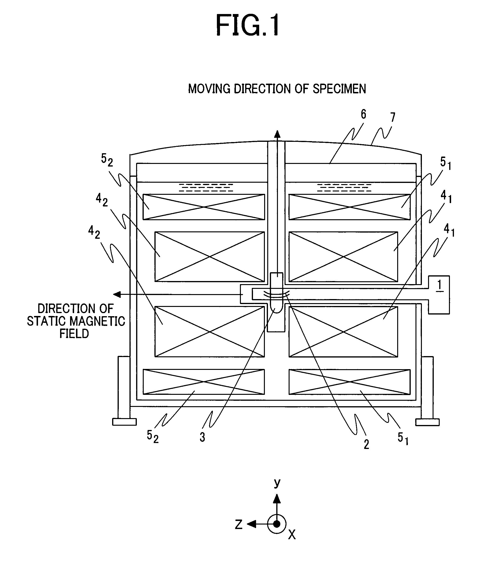
[0025]FIG. 1 is a sectional view showing the overall configuration of a nuclear magnetic resonance apparatus including a probe coil in accordance with the first embodiment. Reference numerals 41 and 42 denote solenoid coils that are produced by bisecting a coil and used to apply a static magnetic field and that are placed sideways. Reference numerals 51 and 52 denote solenoid coils that are produced by bisecting a coil and disposed on the peripheries of the solenoid coils 41 and 42 respectively for the purpose of correcting a magnetic field. The coils are mounte...

second embodiment

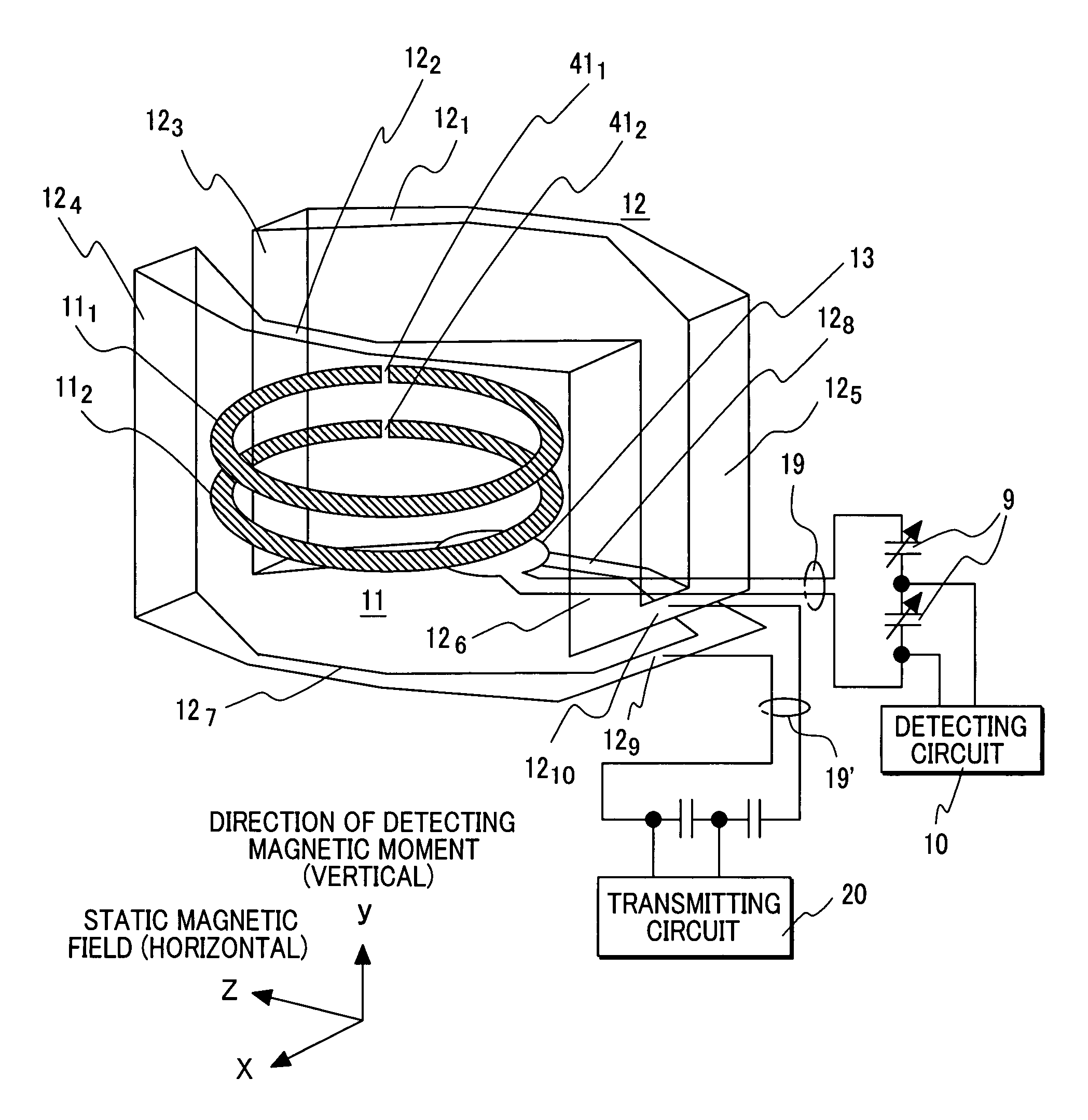
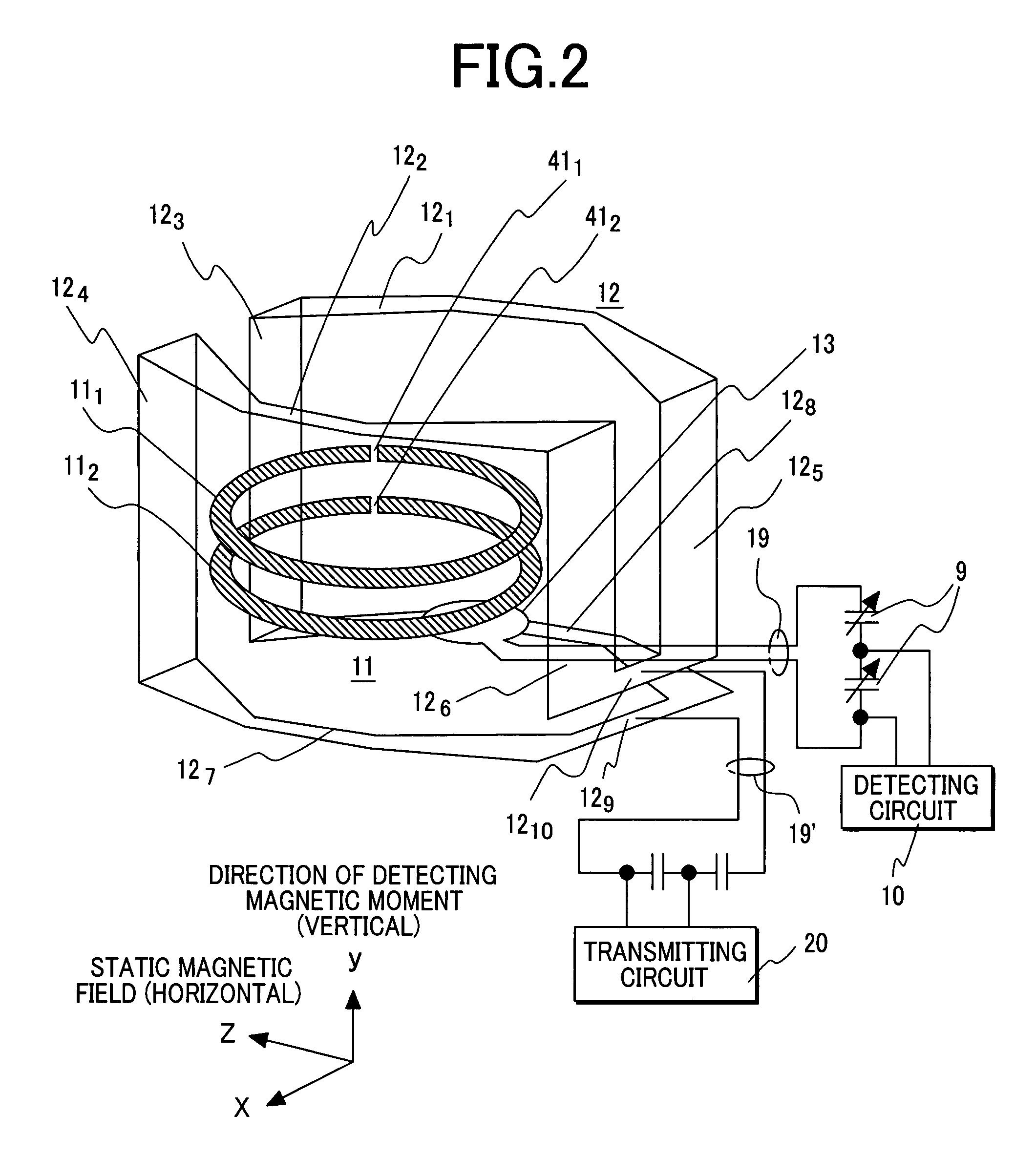
[0046]Next, the second embodiment of the present invention will be described below. The overall configuration of a nuclear magnetic resonance apparatus in accordance with the second embodiment is identical to that of the nuclear magnetic resonance apparatus in accordance with the first embodiment including the probe coil shown in FIG. 3 except a point that the structure of a reception coil is different from that of the reception coil 11 shown in FIG. 3 and employed in the first embodiment. FIG. 5A and 5B are a side view and a plan view respectively which illustratively show the structure of a probe coil 2 in accordance with the second embodiment. However, for a better understanding, the plan view shows the structure with a sapphire substrate 261, on which a superconducting thin-film ring 111 is formed, and sapphire substrates 263 and 265, which are located above the sapphire substrate 261, excluded therefrom.

[0047]As readily seen from the comparison of FIG. 5 with FIG. 3, although t...

third embodiment

[0050]Next, the third embodiment of the present invention will be described below. The overall structure of a nuclear magnetic resonance apparatus in accordance with the third embodiment is identical to that of the nuclear magnetic resonance apparatus in accordance with the first embodiment including the probe coil shown in FIG. 3. The third embodiment is different from the first embodiment in a point that a probe coil 2 is designed to measure two nuclear species. FIG. 6A and FIG. 6B are a side view and a plan view respectively which illustratively shows the structure of the probe coil 2. For a better understanding, the plan view shows the structure with sapphire substrates, on which respective superconducting thin-film rings 11 are formed, ignored.

[0051]As readily seen from the comparison of FIG. 6 with FIG. 3, although the first embodiment uses the pair of superconducting thin-film rings 111, 112 to form the reception coil composed of superconducting thin-film rings contained in r...


PUM


Abstract

Provided is a nuclear magnetic resonance probe coil that is included in a nuclear magnetic resonance apparatus in which the direction of a static magnetic field is horizontal and that can highly sensitively measure multiple nuclear species. A nuclear magnetic resonance apparatus includes a unit that horizontally applies a static magnetic field, a unit that vertically moves a specimen to a predetermined position in the apparatus, and a probe including in the distal part thereof a probe coil that applies a radiofrequency signal to the specimen and that detects a signal produced by the specimen. The probe coil includes multiple pairs of superconducting thin-film rings formed on respective substrates that are disposed in parallel with the static magnetic field while being separated from each other by a predetermined distance, a detection loop that detects a signal received by the superconducting thin-film rings, and a transmission coil that applies the radiofrequency signal to the specimen and that has the normal thereto extended horizontally.

Description

CLAIM OF PRIORITY[0001]The present invention claims priority from Japanese application JP 2006-145006 filed on May 25, 2006, the content of which is hereby incorporated by reference on to this application.BACKGROUND OF THE INVENTION[0002](1) Field of the Invention[0003]The present invention relates to the structure of a nuclear magnetic resonance probe that is included in a nuclear magnetic resonance (NMR) apparatus composed at least of a superconducting magnet which is a means for applying a static magnetic field to a specimen and a low-temperature probe having a probe coil formed in the distal part thereof, and that has the probe coil thereof realized with superconducting thin films formed on respective substrates.[0004](2) Description of the Related Art[0005]The structure of a nuclear magnetic resonance probe coil realized with superconducting thin films has been discussed in, for example, “Review of Scientific Instruments” (Vol. 69, 1998, pp. 2708-2712) or the specification of U...

Claims


Application Information

Patent Timeline
Patent Type & Authority Patents(United States)
IPC IPC(8): G01V3/00
CPCG01R33/34053G01R33/34069G01R33/3415G01R33/3806G01R33/34007G01R33/34023G01R33/3657
Inventor HASEGAWA, HARUHIROYAMAMOTO, HIROYUKISAITOH, KAZUO
Owner HITACHI LTD
Why Eureka
Try Eureka