Document Sheet With Recessed Cavity and Window Two-Sided Printing of an Object Received Therein

Inactive Publication Date: 2007-11-29
EDWARDS PAUL R
View PDF27 Cites 8 Cited by
  • Summary
  • Abstract
  • Description
  • Claims
  • Application Information

AI Technical Summary

Benefits of technology

[0008] The document sheet described herein provides a document sheet with a object thereon affixed in a manner designed to permit removal, having simplified inexpensive construction and having a reduced cross-sectional thickness enabling use of the sheet in printers without the risk of jamming the printer. The document sheet also allows both sides of the object to be printed prior to its removal from the sheet with preferably at least 60% of the rear surface being accessible for printing through the use of an indentation window.
[0009] The document sheet of the present invention is basically comprised of a sheet of material, preferably paper stock, having an indentation area in the shape of a frame recessed in its front surface and an object secured in a portion of the indentation area such that both the front and back sides of the object may be printed without having to remove the object from the indentation.
[0013] With the object being adhered to the indentation surface, a portion of the object's thickness is recessed into the indentation depth so that only a fraction of the object's thickness projects above the front surface of the sheet. This reduces the projection of the object from the front surface of the sheet and lessens the risk of the sheet and object jamming a conventional printer than heretofore has been available with prior art document sheets having cards affixed to their front surfaces. By forming the indentation area in the sheet front surface by debossing the material of the sheet, the document sheet of the invention may be produced more economically than prior art document sheets and business forms comprising underlayment layers beneath cards or labels cut into the thickness of the document sheet.
[0014] Further, the arrangement of the indentation area to include a hole, window, or similar cut-out through the indentation surface, allows access to a portion of the surface of the object that is adjacent the sheet. In this way, both sides of the object may be printed without having to remove the object from the sheet. This allows for more economical printing as the object does not need to be detached and reattached to print both sides, both sides of the object may be printed, and the object may be printed on both sides using standard duplex or other two-sided printing techniques.

Problems solved by technology

Prior art document sheets and business forms of the type having data cards adhered to their front surfaces have been found to be disadvantaged in that the projecting height or thickness of the data card from the front surface of the sheet will, at times, cause the sheet to jam in a printing apparatus.
The cost of the underlayment and its attachment to the underside of the label and sheet contribute significantly to the overall cost of the document sheet.
Further, because of the underlying support section, it is not generally possible to print on the rear of the label because the supporting sheet is in the way.
The problems with these windows has been that generally they only allow a small printable area of the rear to be printed while the entire front can be printed.
In particular, those forms which have windows only allow about 50% of the back area to be printed with only about 65% of any given dimension available.
While this is acceptable for many applications, it is regularly insufficient as the area is centered in the back of the card and the surrounding white space can make the printed area appear odd.
Further, there is by necessity, a lot of unused space which cannot be printed.
Further, those forms attempting to increase printable area on the back regularly have to use tape or other underlying support, again increasing the risk of jam.

Method used


Image

  • Document Sheet With Recessed Cavity and Window Two-Sided Printing of an Object Received Therein
  • Document Sheet With Recessed Cavity and Window Two-Sided Printing of an Object Received Therein
  • Document Sheet With Recessed Cavity and Window Two-Sided Printing of an Object Received Therein

Examples


Embodiment Construction

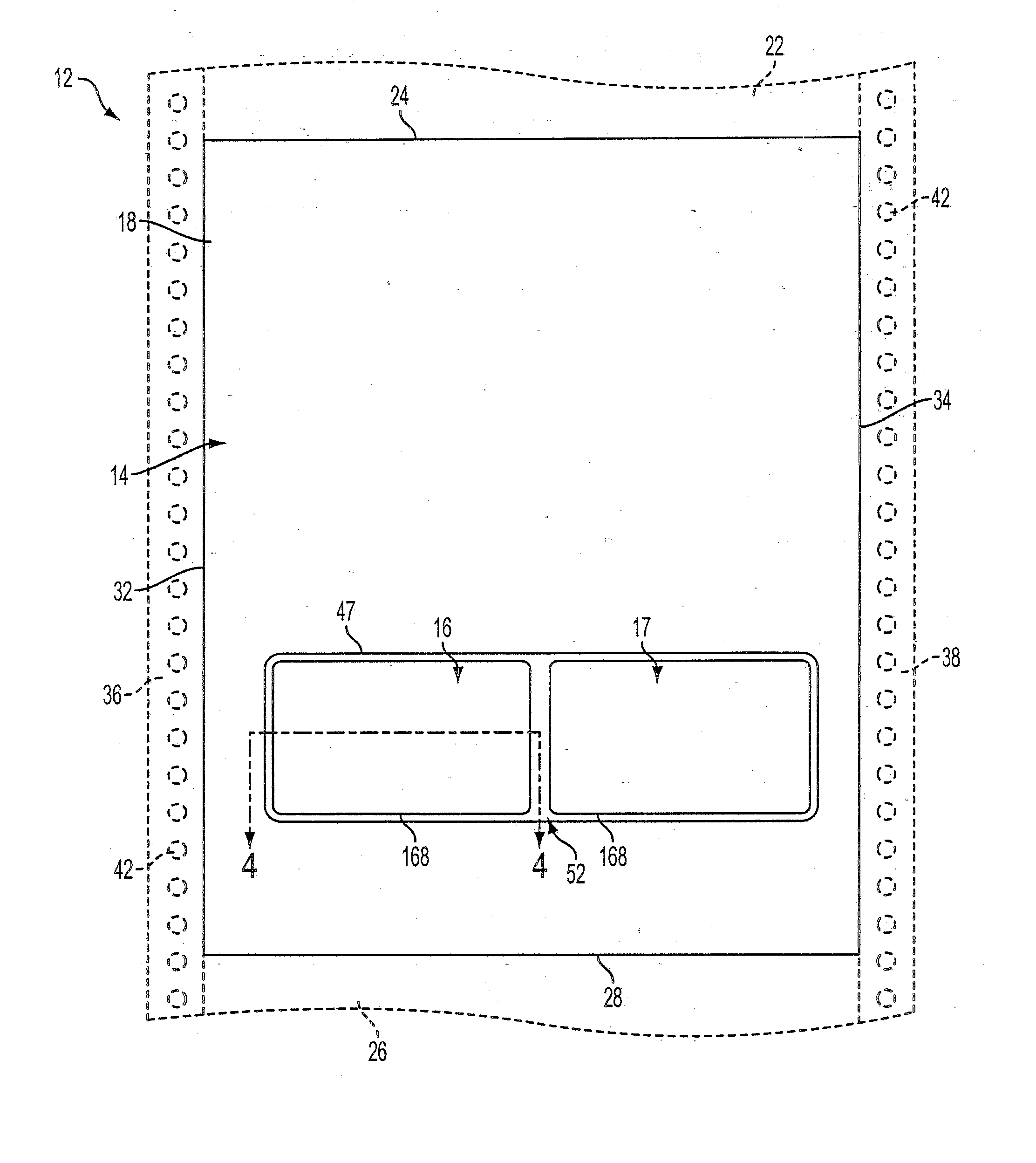
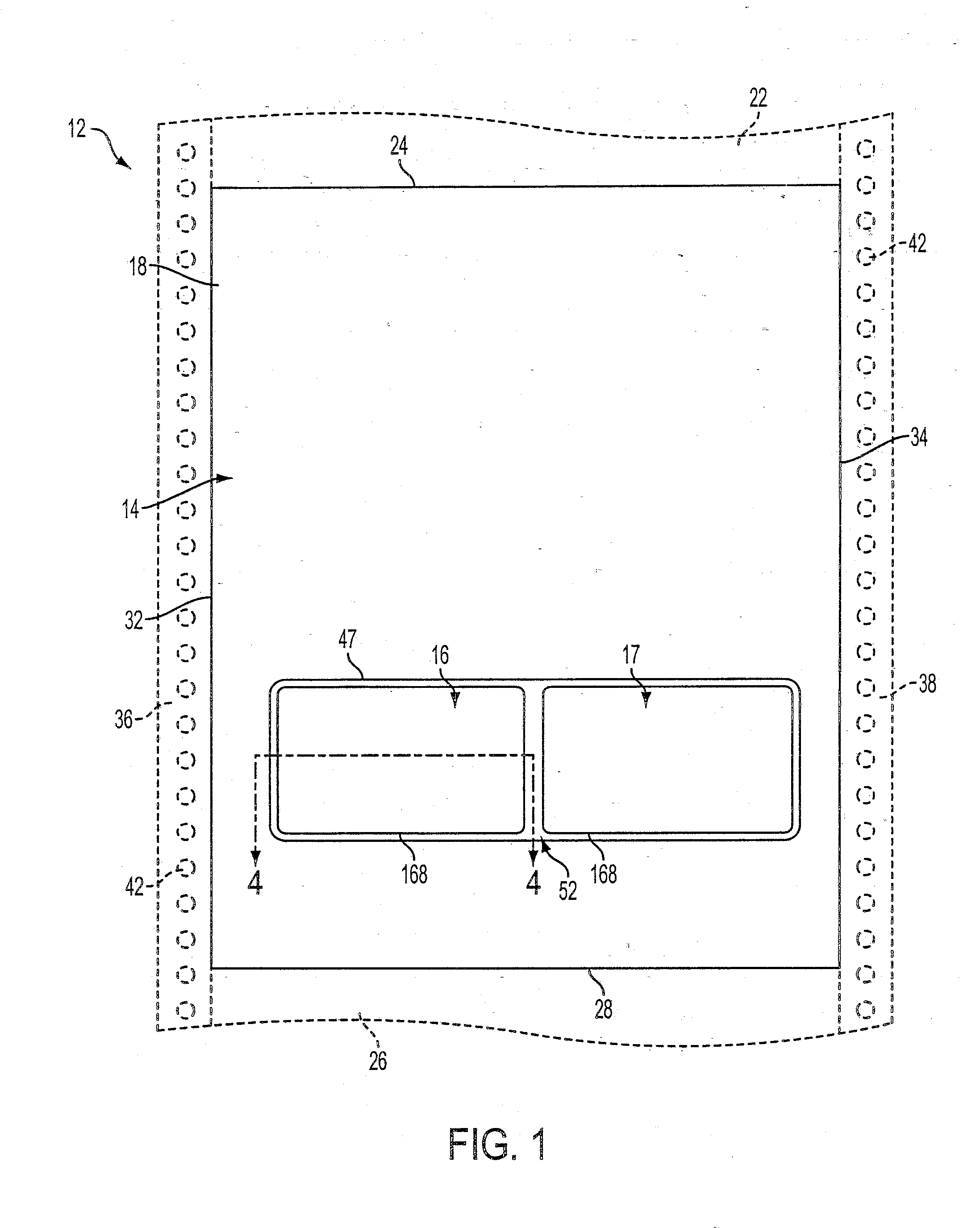
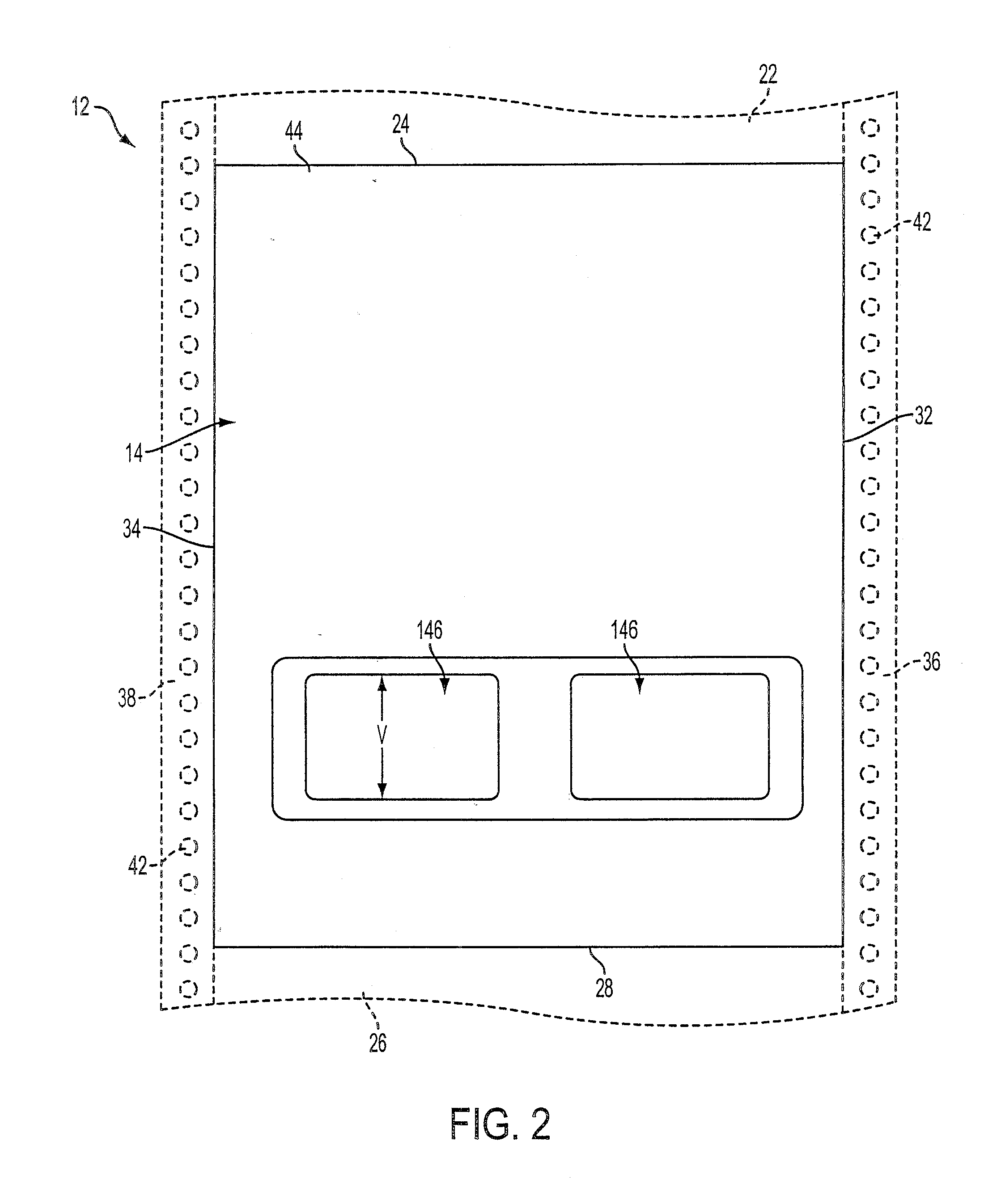
[0023]FIGS. 1 through 4 show different views of an embodiment of a document sheet (12) constructed in accordance with a method so as to provide at least 60% of the back of the object to be available for printing. The document sheet (12) of this embodiment is basically comprised of a sheet of material (14) and two objects (16) and (17) adhered to the front surface (18) of the sheet. While two objects (16) and (17) are shown in this embodiment, one of ordinary skill in the art would understand that one or more objects may be included in different embodiments of the invention. The sheet of material (14) is shown in solid lines in FIG. 1 as a single sheet. However, in variant embodiments of the invention, the sheet of material (14) may be one of a continuous web of material sheets with a second (22) and additional like sheets connected along a top peripheral edge (24) of the sheet and a third (26) and additional like sheets connected along a bottom peripheral edge (28) of the sheet.

[00...


PUM


Abstract

A document sheet with a removably attached object thereon having simplified inexpensive construction and having a reduced cross-sectional thickness enabling use of the sheet in printers without the risk of jamming the printer. The document sheet also allows both sides of the object to be printed prior to its removal from the sheet with preferably at least 60% of the rear surface being accessible for printing through the use of an indentation window.

Description

CROSS REFERENCE TO RELATED APPLICATION(S) [0001] This application is a continuation of U.S. application Ser. No. 10 / 851,801, filed May 21, 2004, which in turn claims benefit of U.S. Provisional Application Ser. No. 60 / 472,551, filed May 22, 2003. The entire disclosure of both documents are herein incorporated by reference. BACKGROUND OF THE INVENTION [0002] (1) Field of the Invention [0003] The present invention pertains to a document sheet or a business form that is formed as a single sheet or part of a continuous web of interconnected sheets, where an indentation(s) are debossed into a front surface of the sheet and an object, such as a card, label, or coin, is releasably adhered to the sheet in the indentation. The indentation being in the shape of a frame with the periphery of the object connected to the indentation so as to enable the printing of both sides of both the document sheet and object. [0004] (2) Background of the Invention [0005] It is well known in the prior art to ...

Claims


Application Information

Patent Timeline
IPC IPC(8): B32B29/00
CPCG09F3/20B41J3/60Y10T428/14B42D5/027B42P2241/22B41J13/12G09F2003/0201Y10T428/249921
Inventor EDWARDS, PAUL R.
Owner EDWARDS PAUL R
Why Eureka
Try Eureka