
Arch assembly for door frame

a technology for door frames and arches, applied in the direction of arched girders, building components, constructions, etc., can solve the problems of inapplicability, cost and/or labor effectiveness, laborious, and time-consuming, and achieve the effect of fast and easy achievemen

Inactive Publication Date: 2007-12-06
RONJO
View PDF21 Cites 2 Cited by
  • Summary
  • Abstract
  • Description
  • Claims
  • Application Information

AI Technical Summary

Benefits of technology

[0014] Another advantage of the present invention is to provide a new and improved method for constructing an arch-shaped passageway which can be accomplished quickly and easily.
[0015] Still another object of this invention is to provide a prefabricated cove arch having a body of unitary construction made of a durable, light material.

Problems solved by technology

The construction of the arches in doorways, or passageways, can be tedious, expensive and time-consuming work and requires a skilled professional, such as, for example, a carpenter.
This design is not practicable and is not cost and / or labor effective because it requires multitude of additional component, i.e. the strip to interconnect the side walls and the base wall, which increases the labor cost.
The unitary structure of the arch-shaped passageway is not compact and flexible in assembly.
Damage of at least one of the front panel, the rear panel and the arcuate panel portion requires replacement of the entire arch-shaped passageway.
In practice, the seam between adjacent drywall and the foam arch has been found to display cracking due in part to the use of dissimilar materials at the seam thereby requiring future repair and maintenance.
Also, the subsequent movement of nailheads outwardly and away from the foam archway creates an unsightly appearance requiring further maintenance.
The prefabricated archway taught by the U.S. Pat. No. 4,601,138 to Hampton is not practicable and is not cost and / or labor effective because it requires multitude of additional component, i.e. the series of nails to interconnect the components of the archway thereby increasing the labor cost.
This modification to the construction of prefabricated archways is required because of the incompatibility of foamed plastic material with the wall-defining materials used in normal construction techniques.
While the molded foam prefabricated archways accomplish the goal of eliminating the construction of coarse archway forms at the construction site, the problems arising from the use of a foamed material such as seam parting, cracking, nail popping and limited resistance to applied pressure remain.
The arch taught by the U.S. Pat. No. 5,572,834 is not practicable and is not cost and / or labor effective because it requires plurality of redundant operations and components to interconnect the throat with the side walls.

Method used


Image

  • Arch assembly for door frame
  • Arch assembly for door frame
  • Arch assembly for door frame

Examples


Embodiment Construction

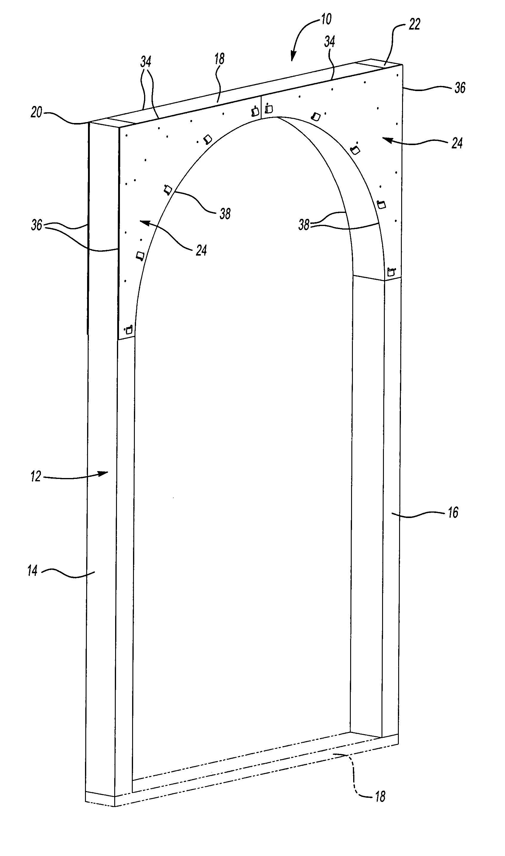
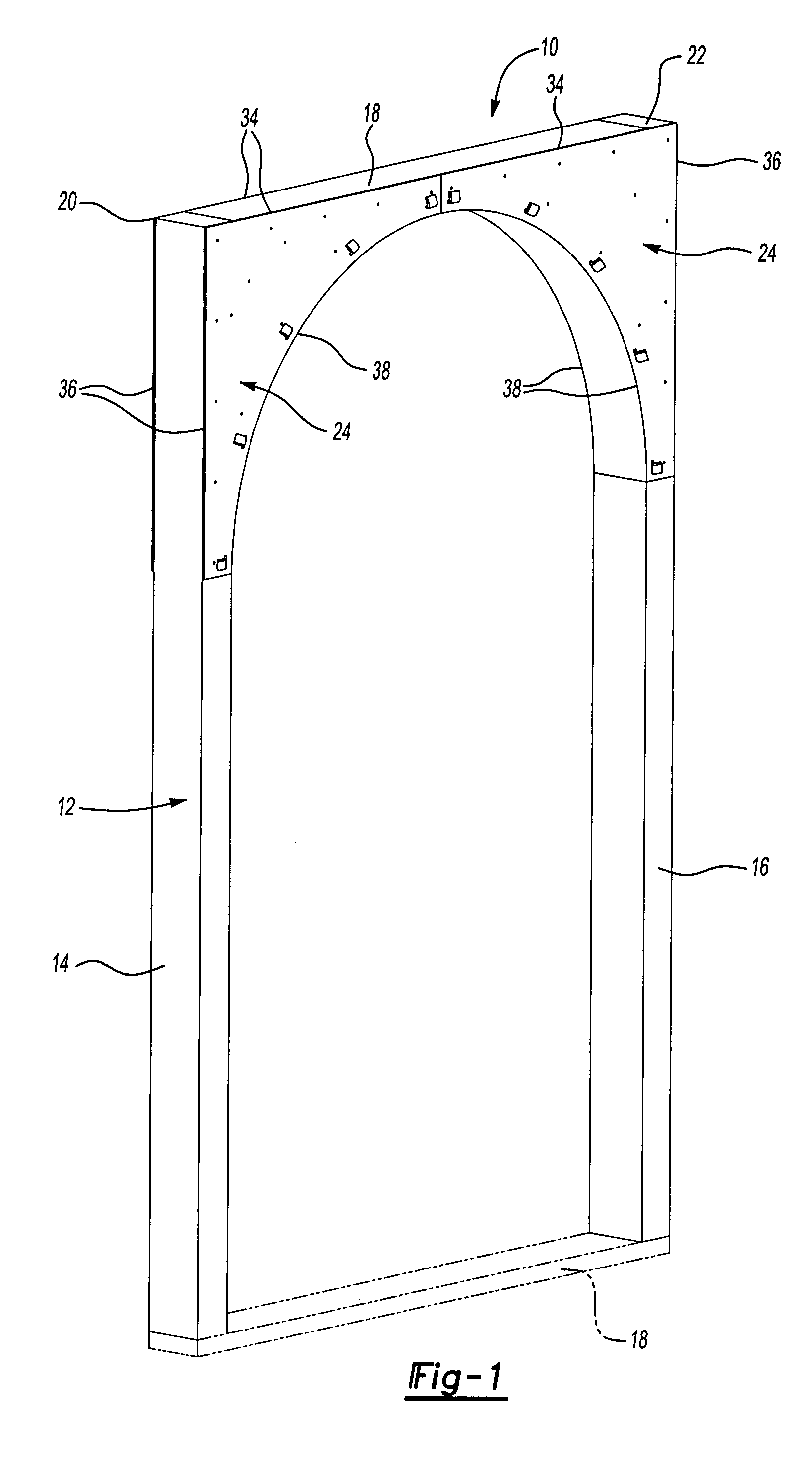
[0028] Referring to the FIG. 1, wherein like numerals indicate like or corresponding parts, an arch assembly (the assembly) of the present invention is generally shown at 10. The assembly 10 is designed to form an archway in walls or door frame, generally indicated at 12, formed by a pair of vertical beams 14 and 16 and at least one horizontal beam 18, which as used in construction sites. As appreciated by those skilled in the construction art, the vertical beams 14 and 16 are interconnected by the horizontal beams 18 to define at least two corners 20 and 22 of the door frame 12 each defining the angle of 90 degrees.

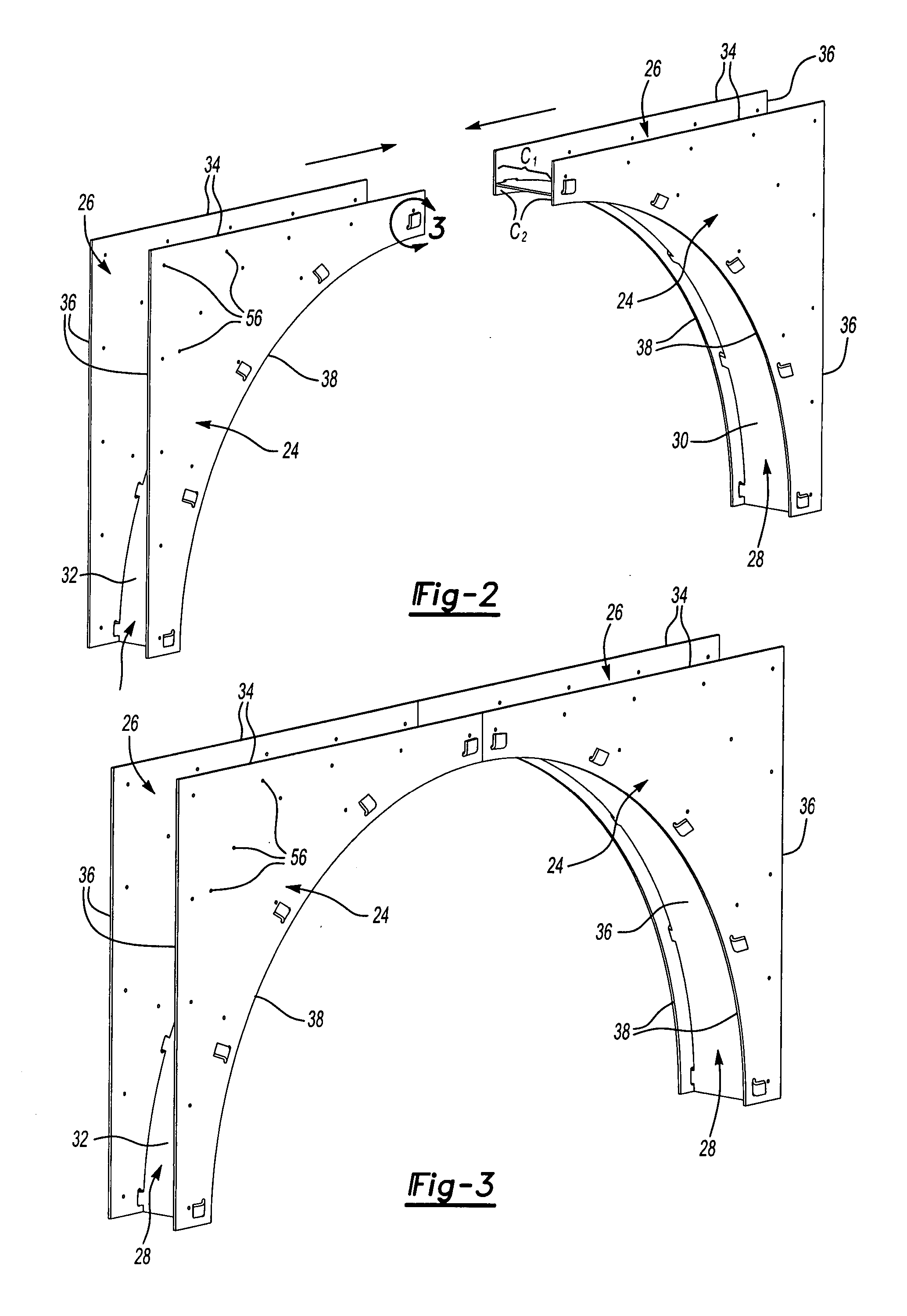
[0029] The assembly 10 may be formed by a pair of arches with each of them including three components such as a pair of side walls or panels, generally indicated at 24 and 26 and a base wall or panel, generally indicated at 28 having inner and outer surfaces 30 and 32. The base wall 28 is connected to and extends between the side walls 24 and 26. Each side wall 24 and 2...


PUM


Abstract

An assembly includes a pair of side walls and a base wall connected to and extending between the side walls. Each side wall has a triangular configuration defined by a pair side edges and an arcuate edge extending between the side edges. A plurality of first connectors, i.e. openings are defined in each of the side walls and are spaced along the arcuate edge. The base wall presents two sides and a plurality of second connectors, i.e. tabs that extend outwardly from each of the sides. The male connectors are coupled with the female connectors to form the arch assembly.

Description

FIELD OF THE INVENTION [0001] This non-provisional application claims priority to provisional application Ser. Nos. 60 / 744,633 filed on Apr. 11, 2006 and 60 / 745,474 filed on Apr. 24, 2006 and incorporated herewith by reference in its entirety.FIELD OF THE INVENTION [0002] The subject invention relates to an arch assembly used in construction of an archway. BACKGROUND OF THE INVENTION [0003] Typically, an arch is used in assembly of a wooden support, i.e. door frame at the construction site. The construction of the arches in doorways, or passageways, can be tedious, expensive and time-consuming work and requires a skilled professional, such as, for example, a carpenter. [0004] The art is replete with various designs and methods of forming and assembling the arches used in construction of buildings. Numerous methods of making the arches are taught by the U.S. Pat. No. 3,008,273 to Widin; U.S. Pat. No. 4,400,917 to Massaro et al.; U.S. Pat. No. 4,601,138 to Hampton; U.S. Pat. No. 4,665...

Claims


Application Information

Patent Timeline
Patent Type & Authority Applications(United States)
IPC IPC(8): E06B1/04
CPCE04C3/38
Inventor PRATER, RONALD
Owner RONJO
Learn More