
Load lift system and method

a technology of a load-lifting system and a load-lifting device, which is applied in the field of weighing systems, can solve the problems of difficult installation of the lift and weighing system, inability to easily adapt to different vehicle makes, and inability to easily replace the weight-measuring device, etc., and achieves the effects of easy installation and/or replacement, high accuracy, and low cos

Active Publication Date: 2007-12-06
SANTI LARRY D
View PDF10 Cites 25 Cited by
  • Summary
  • Abstract
  • Description
  • Claims
  • Application Information

AI Technical Summary

Problems solved by technology

Therefore, installation of the lift and weighing system is typically an arduous task, generally requiring at least one day or days of work.
Installation is typically made difficult by the amount of welding required to secure the lift and weighing system, including the load cells, onto the adaptors of the hydraulically operated arms.
Past solutions have not addressed easy replacement of the weight-measuring devices and adaptability to different types and makes of vehicles.
These may include retrofitting lift systems by introducing an after market weighing system and altering the lift structure, again requiring excessive down time of the vehicle and increasing costs related to replacement of the lift arms and / or the weighing system.
Generally, there has not been a solution that has alleviated substantial torching, cutting, and welding of a new lift and weighing system.
Therefore, conventional weighing systems continue to require cutting existing structure and / or welding on the new weighing system, typically resulting in at least one day, or in some case, days of down time.

Method used


Image

  • Load lift system and method
  • Load lift system and method
  • Load lift system and method

Examples


Embodiment Construction

[0026] Reference throughout this specification to “one embodiment” or “an embodiment” means that a particular feature, structure or characteristic described in connection with the embodiment is included in at least one embodiment. Thus, the appearances of the phrases “in one embodiment” or “in an embodiment” in various places throughout this specification are not necessarily all referring to the same embodiment. Furthermore, the particular features, structures, or characteristics may be combined in any suitable manner in one or more embodiments.

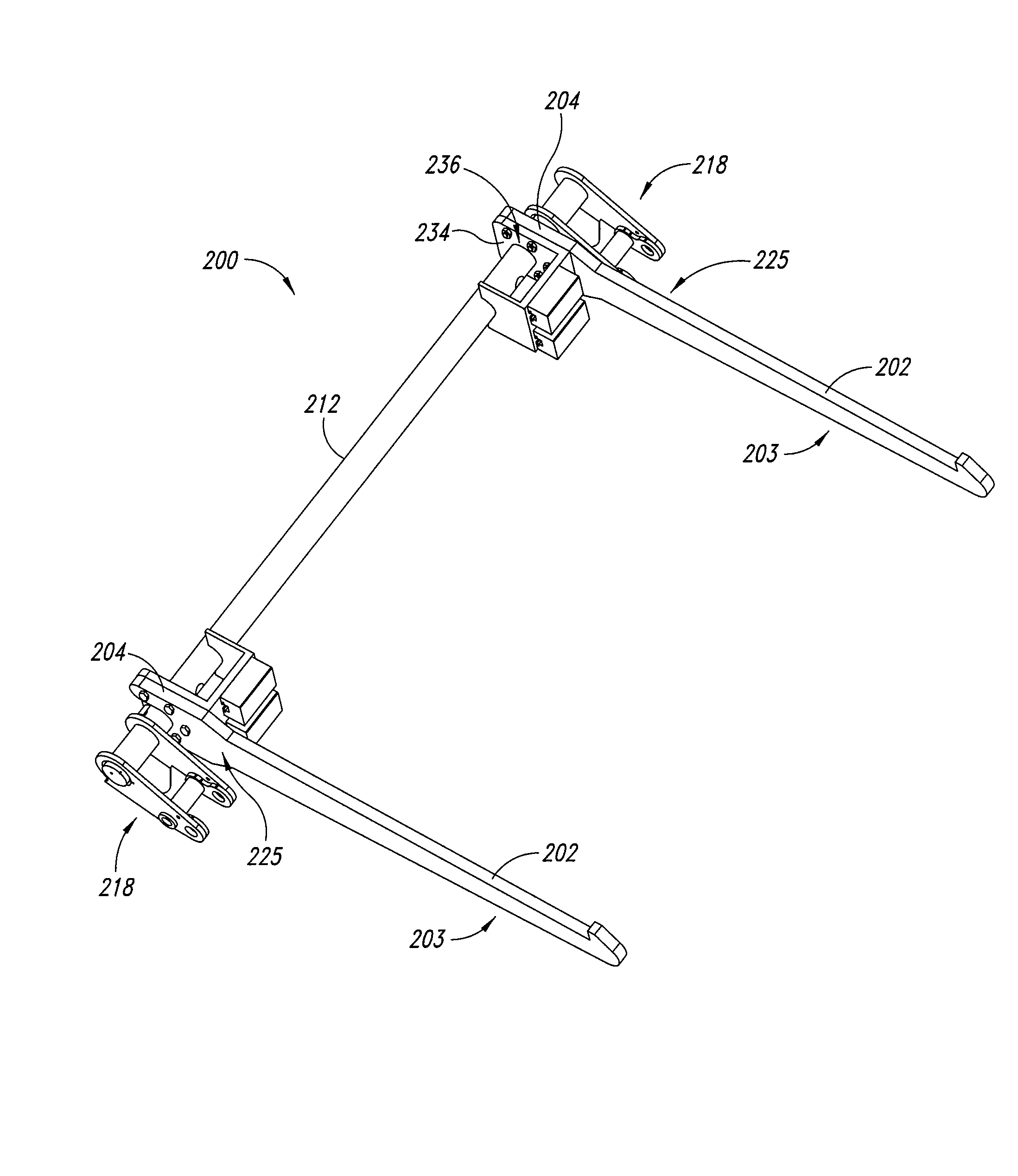
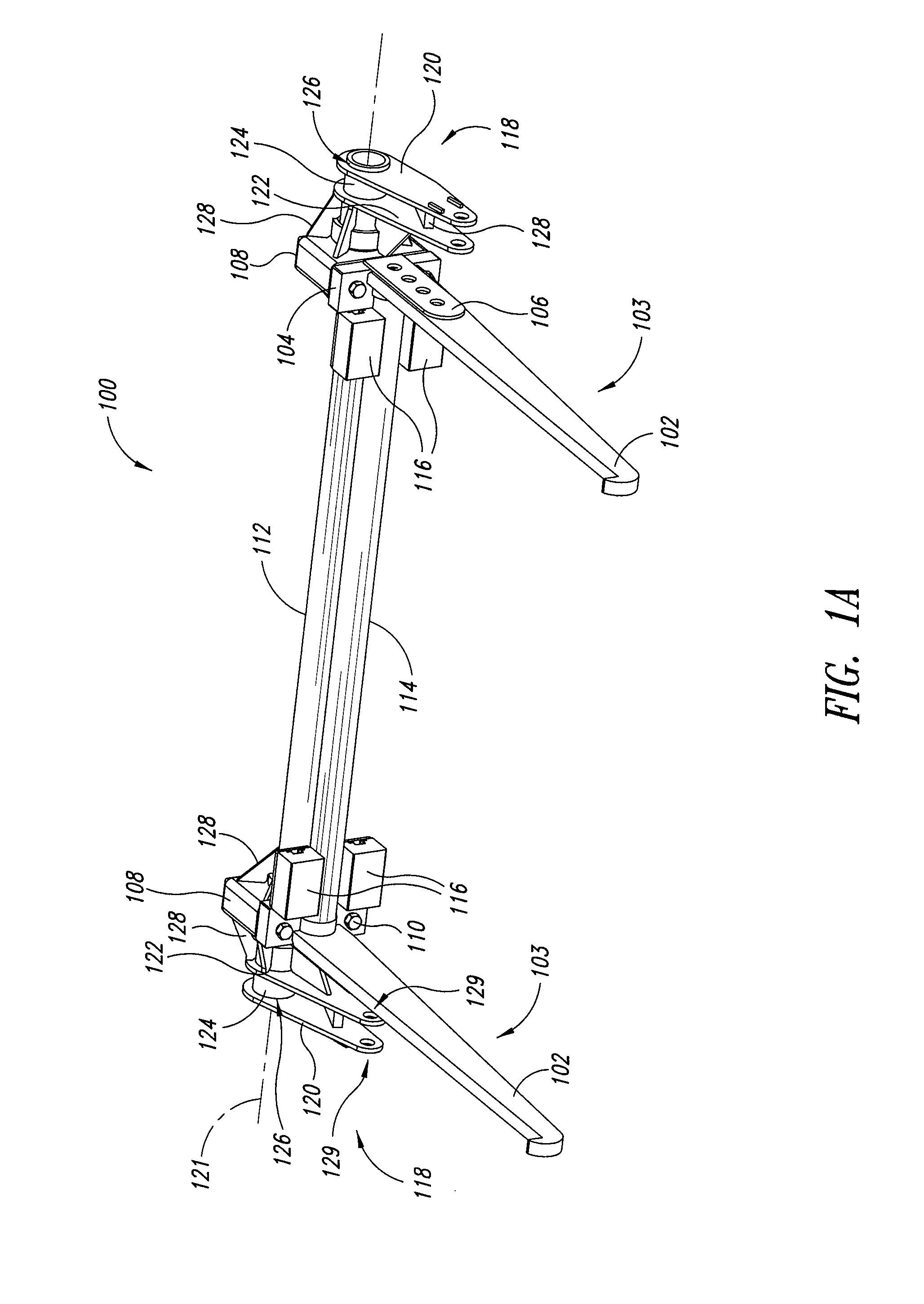
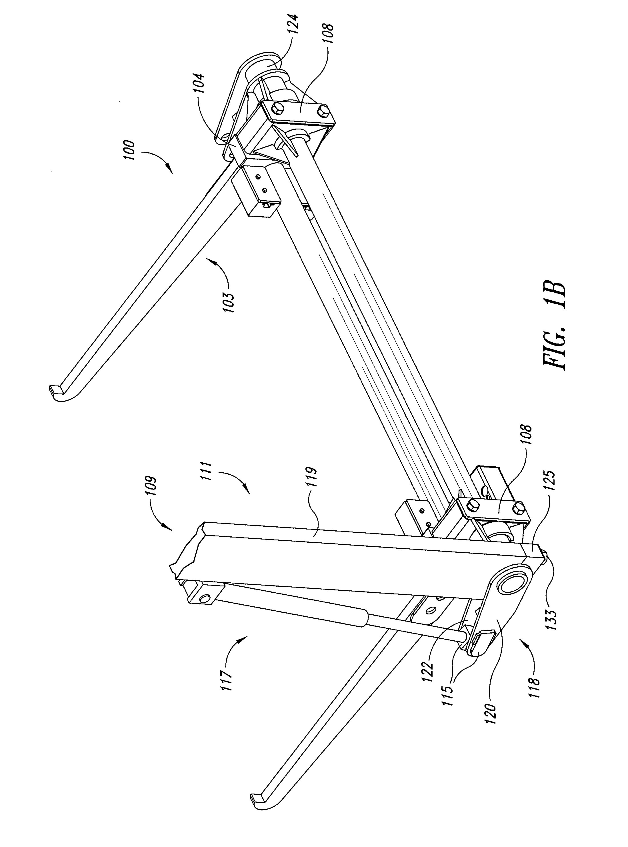
[0027]FIG. 1A illustrates a lift and weighing system 100 according to one embodiment. The lift and weighing system 100 comprises at least two lift arm assemblies 103, each having a base 104 rigidly coupled to a lift arm 102. The lift and weighing system 100 can further comprise at least one optional side brace 106 coupled to each of the two lift arms 102, respectively, to provide additional support to the lift arms 102. In embodiments in whi...


PUM

PropertyMeasurementUnit
timeaaaaaaaaaa
weightaaaaaaaaaa
distanceaaaaaaaaaa

Abstract

A lift and weighing system comprises two lift arm assemblies directly and mechanically coupled to at least two weight-measuring devices. The system may further comprise a first elongated support member extending between and coupling to the two weight-measuring devices, and a second elongated support member interposed between and rigidly affixed on opposing sides thereof to the lift arm assemblies and / or the weight-measuring devices to protect the weight-measuring devices from side loads. The system further comprises at least two end plate adaptors respectively positioned on and rigidly attached toward opposing ends of the elongated support member and adapted to rotatably engage an external actuating system configured to operate the lift and weighing system. In another embodiment, the weight-measuring devices are housed in the elongated support member.

Description

CROSS-REFERENCE TO RELATED APPLICATION [0001] This application claims the benefit under 35 U.S.C. § 119(e) of U.S. Provisional Patent Application No. 60 / 809,958 filed May 31, 2006, where this provisional application is incorporated herein by reference in its entirety.BACKGROUND [0002] 1. Field [0003] The present invention generally relates to weighing systems, and more particularly, to a system and method for weighing loads of a lift while lifting the load. [0004] 2. Description of the Related Art [0005] Load lift systems manufacturers and users generally monitor load weights by incorporating weight-measuring devices and / or systems. Monitoring load weights is desirable to prevent exceeding the maximum load capacity of the lift system. In certain applications, monitoring load weights is also financially desirable in instances where customers are charged based on the weight of the load being delivered, removed, or otherwise handled by the lift system. One example of such applications ...

Claims


Application Information

Patent Timeline
Patent Type & Authority Applications(United States)
IPC IPC(8): G01G19/08
CPCB65F2003/022G01G19/083B65F2003/0279
Inventor SANTI, LARRY D.BOYOVICH, RICHARD
Owner SANTI LARRY D
Learn More