Headlamp cleaner

Inactive Publication Date: 2007-12-06
KOITO MFG CO LTD
View PDF9 Cites 12 Cited by
  • Summary
  • Abstract
  • Description
  • Claims
  • Application Information

AI Technical Summary

Benefits of technology

[0013]It is an object of the present invention to provide a headlamp cleaner in which a weig

Problems solved by technology

However, when a rubber hose is used as the hose 60 which couples the motor pump 52 and the respective nozzles 54, 56 in the headlamp cleaner, a pre

Method used


Image

  • Headlamp cleaner
  • Headlamp cleaner
  • Headlamp cleaner

Examples


Example

[0026]Hereinafter, exemplary embodiments of the invention will be explained with reference to the drawings. The following exemplary embodiments do not limit the scope of the invention.

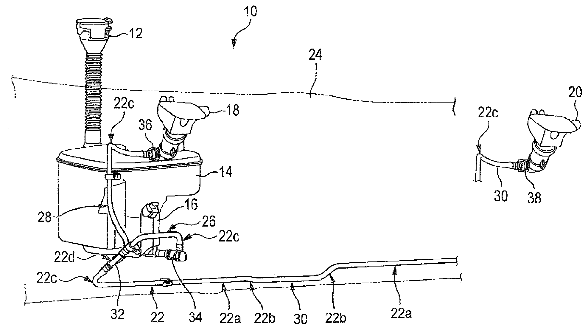
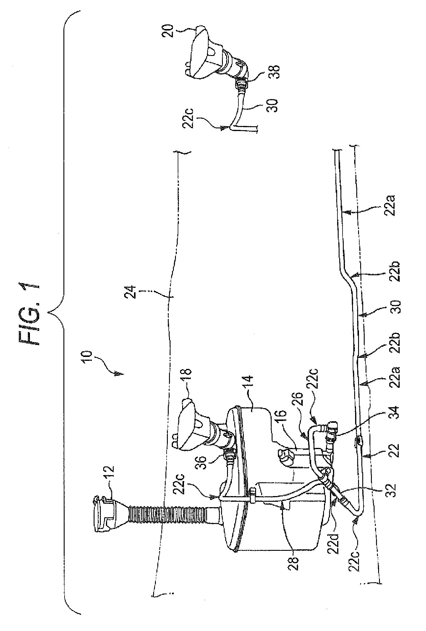
[0027]As shown in FIG. 1, a headlamp cleaner 10 includes a tank 14 in which a cleaning fluid injected from an injecting opening 12 is stored, a motor pump 16 which pumps the cleaning fluid inside the tank 14, a plurality of nozzles 18, 20 which ejects the cleaning fluid pressure-transferred from the motor pump 16 toward respective headlamps (not shown) arranged on right and left sides of a vehicle, and a fluid path 22 which couples the motor pump 16 and the respective nozzles 18, 20. The headlamp cleaner 10 is arranged on a rear side of a vehicle bumper 24.

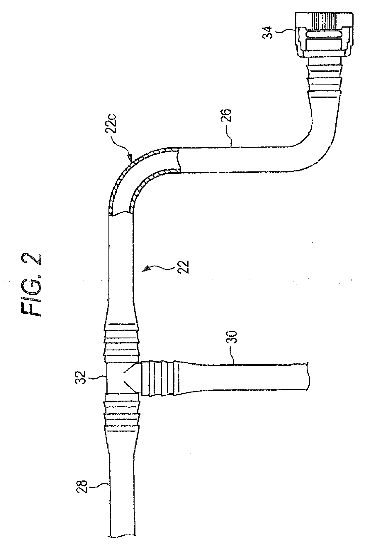
[0028]The fluid path 22 mainly includes plastic hoses 26, 28, 30. The fluid path 22 also includes a T-shaped joint 32 which may be made of polyacetal, and connectors 34, 36, 38. Each of the plastic hoses 26, 28, 30 includes at least one of a linear p...


PUM


Abstract

A headlamp cleaner includes a tank in which a cleaning fluid is stored, a motor pump which pumps the cleaning fluid stored inside the tank, a fluid path through which the cleaning fluid pumped by the motor pump is pressure-transferred, and a nozzle from which the cleaning fluid pressure-transferred through the fluid path is ejected toward a headlamp. The fluid path mainly includes a hose made of a rigid material such as plastic.

Description

[0001]The present invention claims priority from Japanese Patent Applications No. 2006-154309 filed on Jun. 2, 2006, and No. 2007-083537 filed on Mar. 28, 2007, the entire contents of which are incorporated herein by reference.BACKGROUND OF INVENTION[0002]1. Field of the Invention[0003]The invention relates to a headlamp cleaner which ejects a cleaning fluid toward a headlamp of a vehicle to clean the headlamp. More specifically, the present invention relates to an improvement of a fluid path of the headlamp cleaner.[0004]2. Description of the Related Art[0005]Some vehicles, such as cars, are mounted with a headlamp cleaner in order to clean a surface of a headlamp with a cleaning fluid so that the surface of the headlamp is prevented from being unclear due to dirt resulting from, e.g., melted snow. Headlamp cleaners are mounted, in particular, on vehicles used in Europe since it is obligatory to mount a headlamp cleaner for a vehicle employing a discharge lamp in Europe.[0006]When ...

Claims


Application Information

Patent Timeline
IPC IPC(8): B05B1/10A62C11/00
CPCB60S1/481B60S1/603B60S1/50
Inventor SATO, MASAAKISAKAI, MASARU
Owner KOITO MFG CO LTD
Why Eureka
Try Eureka