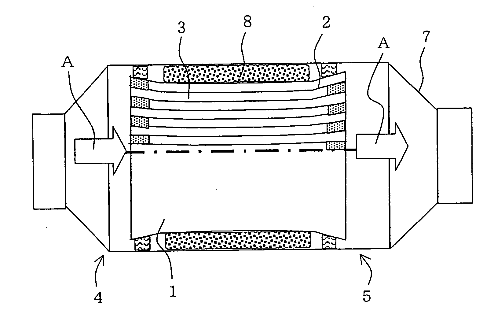
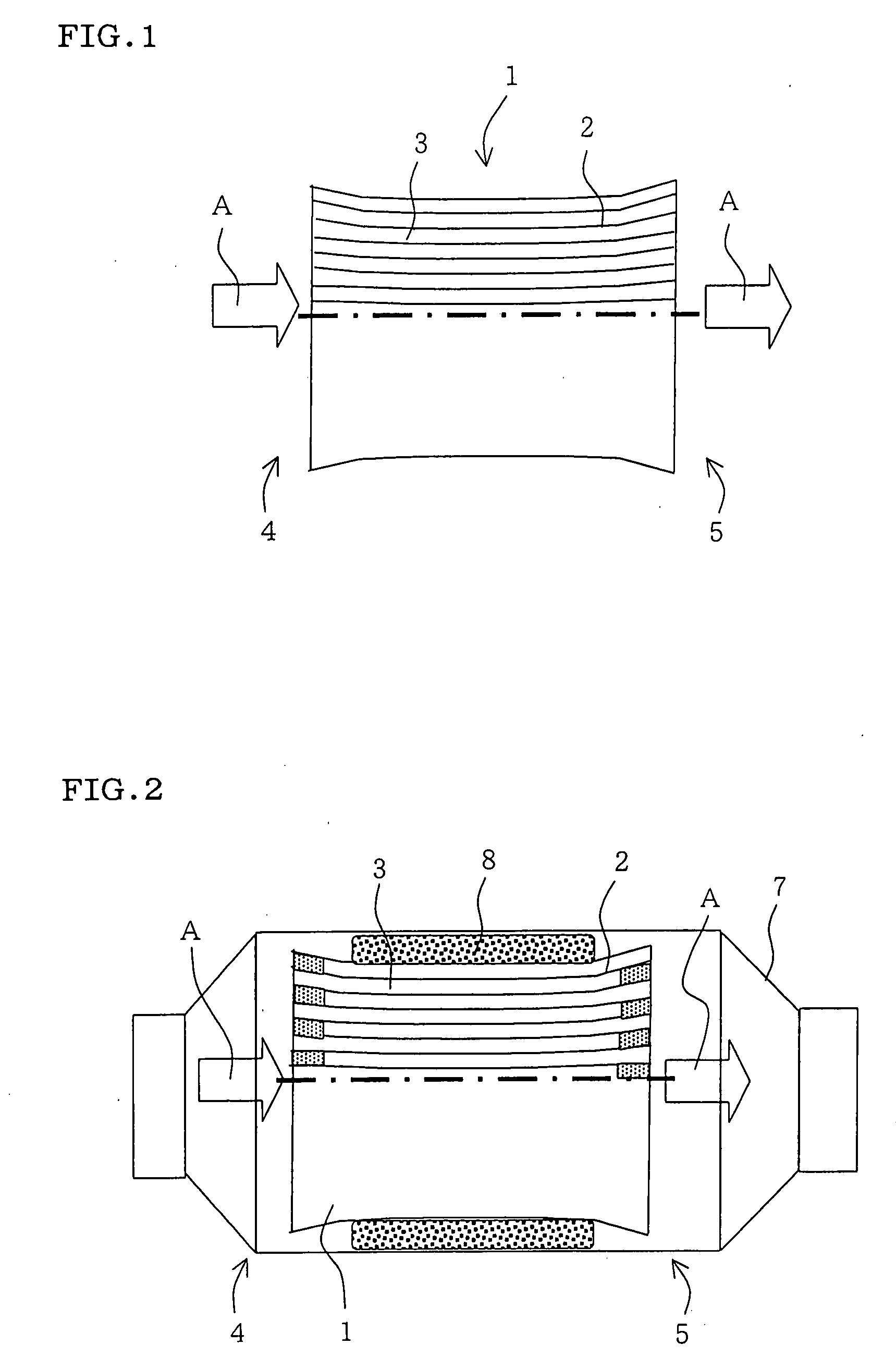
However, in the above-mentioned honeycomb structure wherein the section of cell normal to the flow direction of fluid (this section may hereinafter be referred to as “cell section”) has about the same area over the entire flow direction, there is a problem of the
high pressure loss caused by the fluid incoming resistance at the inlet side end face of honeycomb structure and the fluid outgoing resistance at the outlet side end face.
In order to respond to the recent stricter regulation for exhaust gas, there is a trend of allowing a honeycomb structure to have a higher
cell density for increased surface area and, accordingly, there is a tendency of an increase in pressure loss at the inlet side end face and outlet side end face of honeycomb structure.
This occurs because, when a fluid (e.g. an exhaust gas) enters the cells, a fluid-stagnant portion appears at the cell inlet side end face; the substantial area of cell section through which the fluid can pass decreases sharply, and flow rate changes in this portion causing a fluid loss.
Also at the cell outlet side end face, the area of cell section through which the fluid such as exhaust gas can pass increases sharply and flow rate changes causing a fluid loss.
Also in the
diesel particulate filter (DPF) used for purification of exhaust gas emitted from
diesel engine or the like, there is a problem of the
high pressure loss caused by the exhaust gas incoming resistance at the inlet side end face of honeycomb structure and the exhaust gas outgoing resistance at the outlet side end face.
That is, the captured particulate matter deposits gradually in the filter with its use; the particulate matter adheres to the plugged ends of cells at the inlet side end face of filter; this invites further gradual deposition of particulate matter which leads to plugging of
open cell ends at the inlet side end face of filter; as a result, a sharp increase in pressure loss takes place.
As a result, the open ends of the cells 63a at each
peripheral area are blocked by the
retainer ring 69, making the passage of exhaust gas difficult, which has invited a decrease in the substantial total area of cell sections of honeycomb structure 61 and an increase in pressure loss.
Also in the filter, there is a decrease in the
filtration area of cells 63 having the open ends blocked and this has invited a further increase in pressure loss.
Also, when such a converter 60 is under actual load, there has been a problem that circumferential cracks tend to appear at the
peripheral portion of honeycomb structure 61.
Further, when the honeycomb structure is used as a filter for exhaust gas, there has been a problem that cracks are generated at the vicinity of the exhaust gas inlet side end face of honeycomb structure owing to the
thermal shock caused by the sharp temperature change of exhaust gas.
Cracks are generated in a large amount particularly when the honeycomb structure is mounted in the vicinity of engine where the exhaust gas temperature is relatively high and the temperature change or flow
rate change of exhaust gas is very sharp.
Although not shown by drawing, conventional honeycomb structures also have a problem that, when the
solid foreign matter such as
iron oxide peeled from an
exhaust pipe is carried by an exhaust gas and arrives at the honeycomb structure, the inlet side end face of honeycomb structure tends to cause
erosion.
It has been confirmed that this
erosion takes place easily particularly when the honeycomb structure is mounted near an engine and also when the honeycomb structure has thin partition walls or is made of a material of high
porosity or
large pore diameter.
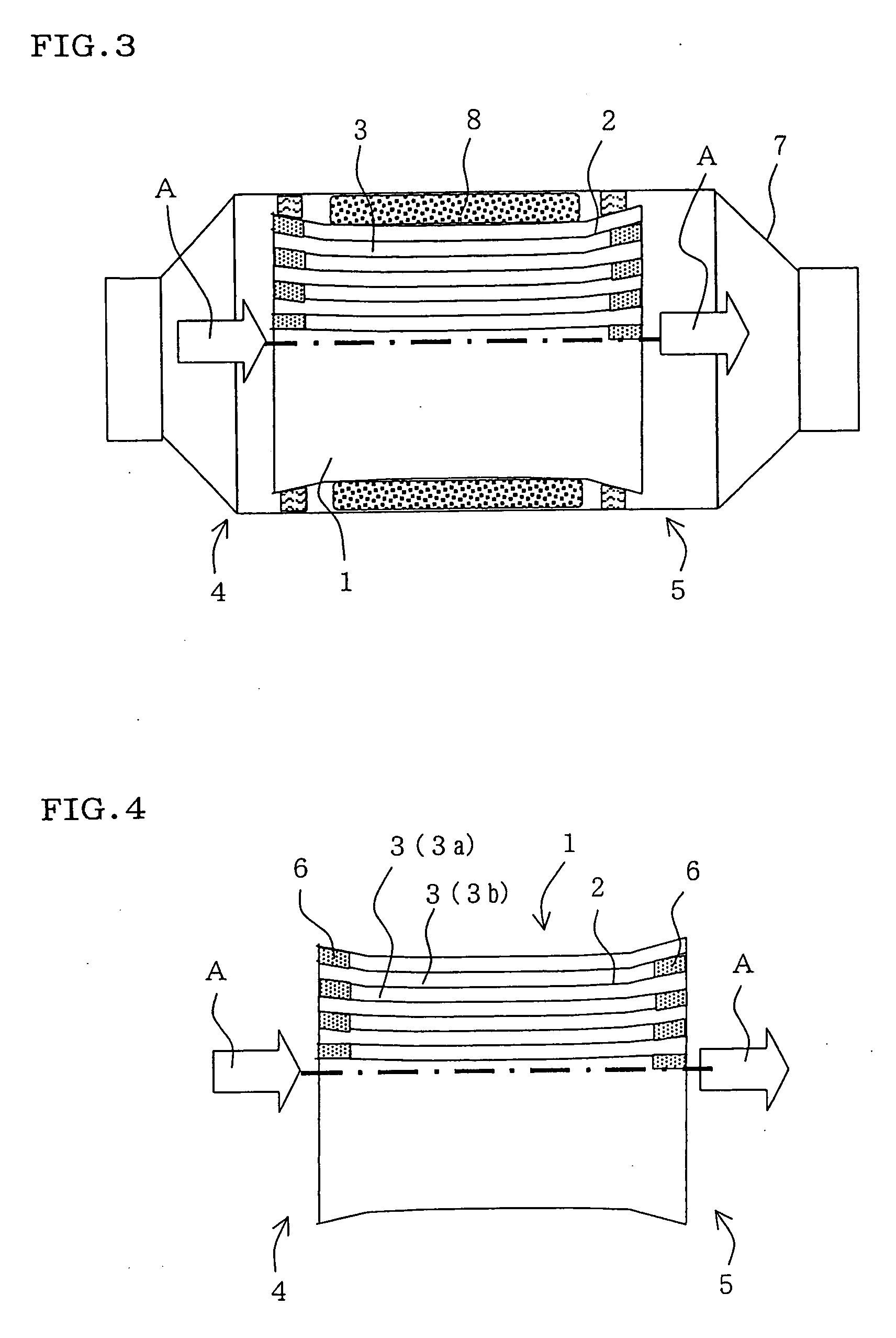
Also, in a honeycomb structure such as shown in the
Patent Literature 3, wherein cell section size is gradually changed over the entire length of honeycomb structure from the inlet side end face to the outlet side end face, there are a problem that cracks appear easily in firing of formed body for production of honeycomb structure and also a problem that it is unable to employ the conventional canning technique using a holding member 68, such as shown in FIG. 30(a) and FIG. 30(b).
