Tourmaline treatment device and cooling water circulation system including same
Active Publication Date: 2019-08-15
TOYOTA BOSHOKU KK
3 Cites 0 Cited by
AI-Extracted Technical Summary
Problems solved by technology
Unfortunately, the tourmaline generates a weak current and a small electric field, so that it is difficult to remarkably obtain the action and effect of the tourmaline as described above by only bringing the tourmaline into contact with water, or by only bringing the tourmaline in contact with water instantaneously or for a short time.
In addition, the tourmaline is a mass of hard rock, so that its handling is limited to cause its usage to be diff...
View moreBenefits of technology
[0028]The tourmaline treatment device of the present invention includes the housing having the inflow port and the outflow port for cooling water, and the container disposed in the housing so as to partition the inside of the housing into the upstream space and the downstream space to contain tourmaline granules; The container includes the upstream partition wall facing the upstream space and the downstream partition wall facing the downstream space. The upstream partition wall is provided with a plurality of inflow holes for allowing cooling water to flow into the container from the upstream space, and the downstream partition wall is provided with a plurality of outflow holes for allowing the cooling water to flow out from the inside of the container into the downstream space. The container further includes flow velocity control means for increasing flow velocity of cooling water passing through the inside of the container. This causes the cooling water flowing into the upstream space in the housing from the inflow port to flow into the container through the plurality of inflow holes of the upstream partition wall to pass through the inside of the container, or among the tourmaline granules. At this time, the flow velocity control means increases the flow velocity of the cooling water passing through the inside of the container. Thus, the cooling water is brought into contact with the tourmaline granules with a strong pressure and impact, so that the piezoelectric effect being the characteristic of the tourmaline is developed to efficiently produce useful tourmaline-treated water. Then, the cooling water having passed through the inside of the container flows out from the plurality of outflow holes of the downstream partition wall into the downstream space in the housing to flow out to the outside of the housing through the outflow port.
[0029]When the flow velocity control means is configured such that the plurality of inflow holes each has an opening area smaller than an opening area of each of the plurality of outflow holes, the cooling water in the upstream space passes through the inside of the container at a flow velocity increased when passing through the inflow holes each having a relatively small opening area. The cooling water having passed through the inside of the container passes through the outflow holes each having a relatively large opening area to reduce increase in pressure loss.
[0030]When the flow velocity contro...
View moreAbstract
The present tourmaline treatment device includes a housing, and a container disposed in the housing so as to partition the inside of the housing into an upstream space and a downstream space and contain tourmaline granules. The container includes an upstream partition wall facing the upstream space and a downstream partition wall facing the downstream space. The upstream partition wall is provided with a plurality of inflow holes for introducing cooling water into the container from the upstream space, and the downstream partition wall is provided with a plurality of outflow holes for allowing cooling water to flow out from the container into the downstream space. The container further includes flow velocity control means for increasing flow velocity of cooling water passing through the inside of the container.
Application Domain
Technology Topic
Image
Examples
- Experimental program(1)
Example
EXAMPLE
[0063]Hereinafter, the present invention will be described in detail using an example with reference to the drawings.
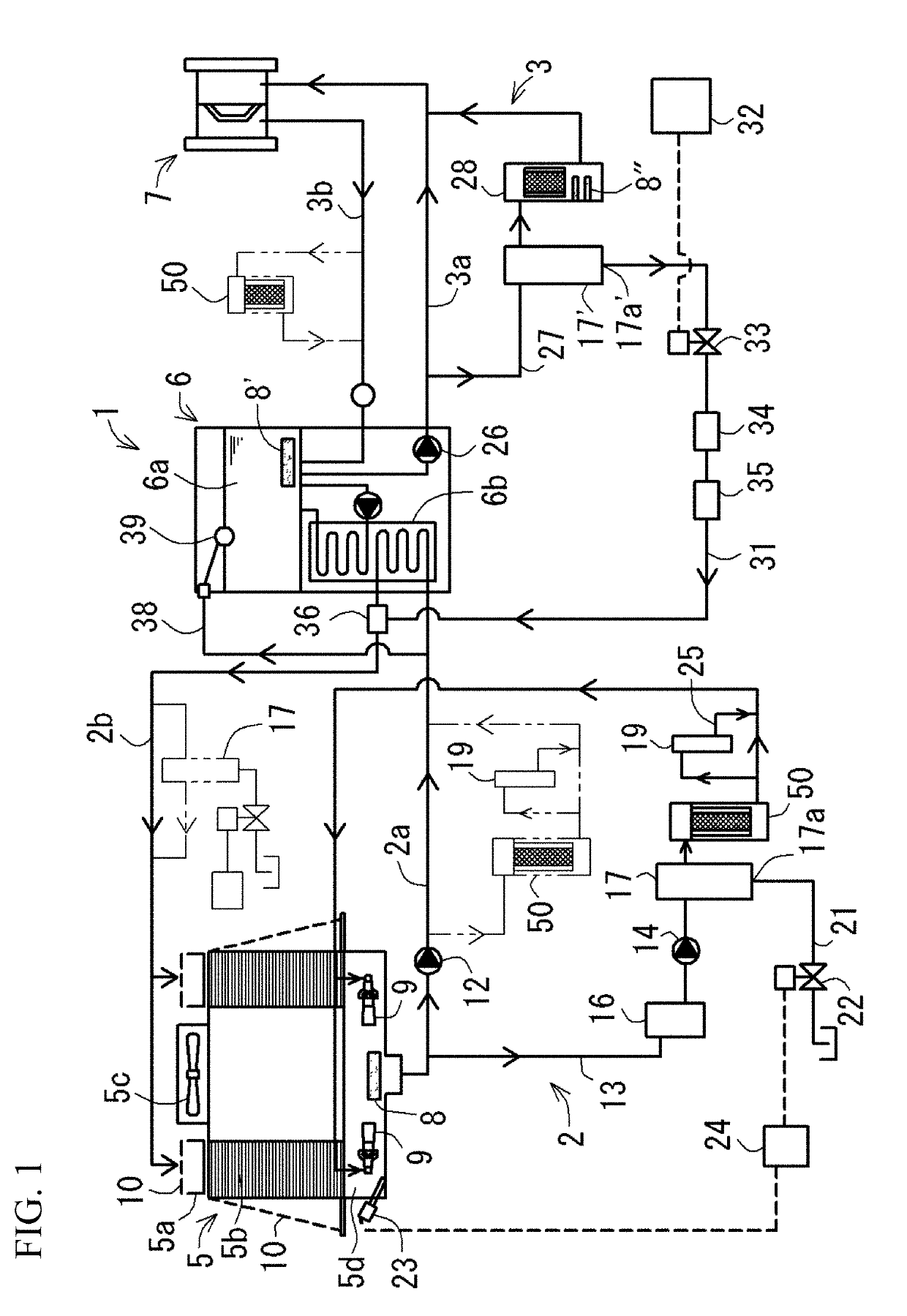
[0064](1) Configuration of Cooling Water Circulation System
[0065]As illustrated in FIG. 1, a cooling water circulation system 1 according to the present example circulates cooling water in a circulation path, and includes a tourmaline treatment device 50 described below. The circulation path includes a cooling-tower-side circulation path 2 for circulating the cooling water between a cooling tower 5 and a chiller machine 6, and a chiller-machine-side circulation path 3 for circulating the cooling water between a chiller machine 6 and a cooling target part 7. Examples of the cooling target part 7 include an injection molding device, a press working device, a welding device, a heating device, a trimming device, and the like.
[0066]The cooling tower 5 includes a water sprinkling tank 5a for storing and sprinkling cooling water increased in temperature fed from the chiller machine 6, a filling material 5b for cooling the water sprinkled from the water sprinkling tank 5a with air, a blower 5c for taking in outside air through a suction port to allow the outside air to pass through the inside of the filling material 5b, and a water tank 5d for storing the cooling water dropped while being cooled by the filling material 5b. The water tank 5d is provided in its inside with a straight pipe 8 made of porous ceramic for generating microbubbles in cooling water by air supply using a compressor (not illustrated), and an injector 9 for removing precipitate precipitating on the bottom of the water tank 5d. In addition, a multifunctional net 10 is stretched so as to cover the suction port and the water sprinkling tank 5a of the cooling tower 5.
[0067]The chiller machine 6 includes a tank 6a for storing cooling water increased in temperature fed from the cooling target part 7, and a heat exchanger 6b for cooling the cooling water in the tank 6a. The tank 6a is provided in its inside with a straight pipe 8′ made of a porous ceramic for generating microbubbles in cooling water by air supply using a compressor (not shown).
[0068]The cooling-tower-side circulation path 2 includes a feed path 2a that is connected at one end to the water tank 5d of the cooling tower 5 and at the other end to the heat exchanger 6b of the chiller machine 6, and a return path 2b that has one end connected to the heat exchanger 6b of the chiller machine 6 and the other end connected to the water sprinkling tank 5a of the cooling tower 5. The feed path 2a is provided with a pressure pump 12 for pumping the cooling water in the water tank 5d of the cooling tower 5 toward the heat exchanger 6b of the chiller machine 6. In addition, an introduction pipe 13 has one end connected to the injector 9 and the other end connected to the feed path 2a upstream of the pressure pump 12. The introduction pipe 13 is provided with a pressure feed pump 14 for pumping the cooling water in the water tank 5d of the cooling tower 5 toward the injector 9. Then, the injector 9 injects the cooling water pumped by the pressure pump 14 to remove precipitate precipitating on the bottom of the water tank 5d.
[0069]The introduction pipe 13 includes a basket filter 16 containing a water treatment agent made of an inorganic substance or the like, a water impurity separation device 17 for removing impurities contained in the cooling water, and a. tourmaline treatment device 50 described below for treating the cooling water with tourmaline granules. The water impurity separation device 17 has a drain port 17a connected to a drain pipe 21 that is opened and closed by an on-off valve 22. The on-off valve 22 is controlled to be opened and closed by a control unit 24 in accordance with a detection value from a sensor 23 for detecting electric conductivity of cooling water. When the drain pipe 21 is opened, the cooling water is discharged together with impurities from the drain port 17a of the impurity separation device 17. The introduction pipe 13 is provided with a bypass path 25, and the bypass path 25 is provided with a magnetic water treatment device 19 for magnetically treating cooling water.
[0070]While the water impurity separation device 17 provided in the introduction pipe 13 is shown in the present example, the present invention is not limited to this. For example, the water impurity separation device 17 may be provided in the return path 2b (or the feed path 2a) of the cooling tower circulation path 2 instead of or in addition to the introduction pipe 13, as illustrated in FIG. 1 by an imaginary line.
[0071]The chiller-machine-side circulation path 3 includes a feed path 3a that has one end connected to the tank 6a of the chiller machine 6 and the other end connected to the cooling target part 7, and a return path 3b that has one end connected to the cooling target part 7 and the other end connected to the tank 6a of the chiller machine 6. The feed path 3a is provided with a pressure pump 26 for pumping cooling water in the tank 6a of the chiller machine 6 toward the cooling target part 7. In addition, a bypass path 27 is provided downstream of the pressure pump 26 in the feed path 3a. The bypass path 27 includes a water impurity separation device 17′ for removing impurities contained in cooling water, and a microbubble generator 28 for generating microbubbles in cooling water.
[0072]The microbubble generator 28 is provided with a straight pipe 8″ made of porous ceramic for generating microbubbles by air supply using a compressor (not illustrated), and has a configuration substantially equivalent to that of the tourmaline treatment device 50. Thus, the microbubble generator 28 also exerts a tourmaline treatment function of treating cooling water with tourmaline granules.
[0073]The cooling-tower-side circulation path 2 and the chiller-machine-side circulation path 3 are connected by a first connection pipe 31 for introducing cooling water circulating in the chiller-machine-side circulation path 3 into the cooling-tower-side circulation path 2. The first connection pipe 31 connects the return path 2b of the cooling-tower-side circulation path 2 to a drain port 17a′ of the water impurity separation device 17′. The first connection pipe 31 is provided with an electric valve 33 of a ball valve type for opening and closing the first connection pipe 31 by opening and closing control of a control unit 32, a constant flow valve 34 of a washer rubber type, and a check valve 35 for preventing a reverse flow of cooling water. The electric valve 33 is controlled to be opened and closed with a timer function of the control unit 32. The first connection pipe 31 is provided at its one end with a differential pressure injector 36 disposed in a pipe constituting the cooling-tower-side circulation path 2.
[0074]The cooling-tower-side circulation path 2 and the chiller-machine-side circulation path 3 are connected by a second connection pipe 38 for introducing the cooling water circulating in the cooling-tower-side circulation path 2 to the chiller-machine-side circulation path. 3. The second connection pipe 38 connects the feed path 2a of the cooling-tower-side circulation path 2 and the tank 6a of the chiller machine 6. The second connection pipe 38 is provided at its one end with a float valve 39 for opening and closing the second connection pipe in accordance with vertical movement of the water surface in the tank 6a.
[0075](2) Configuration of Tourmaline Treatment Device
[0076]As illustrated in FIGS. 2 and 3, the tourmaline treatment device 50 according to the present example includes a housing 52 in a cylindrical shape having an inflow port 51a and an outflow port 51b for cooling water, and a container 53 in a double cylindrical shape that is disposed in the housing 52 so as to divide the inside of the housing 52 into an upstream space S1 and a downstream space S2, and that contains tourmaline granules 55.
[0077]In the present example, a high purity tourmaline produced from a Brazilian mine is used as the tourmaline granules 55, and a raw stone of the tourmaline is polished with a rotating drum for grinding up to about ½ of the raw stone by weight to increase its hardness, thereby preventing crush of the tourmaline. In consideration of circulatory pressure (e.g., 0.3 MPa to 0.5 MPa) of cooling water, the tourmaline granules 55 each in an oval shape having a particle diameter of 3 mm to 5 mm are used.
[0078]The housing 52 includes a housing body 52a in a bottomed cylindrical shape that has an opening at one end side in its axial direction (or at its upper end), and in which the container 53 is disposed, and a lid 52b detachably attached to the housing body 52a so as to cover the opening of the housing body 52a. The housing body 52a has a side wall provided in its upper portion with an inflow port 51a, and an outflow port 51b is provided in a lower portion of a side wall of the housing body 52a, facing the inflow port 51a. The inflow port 51a is provided so as to open while facing a space above the container 53. The outflow port 51b is provided so as to open while facing a side face of the container 53. As illustrated in FIG. 4, the lid 52b is detachable from the housing body 52a when a screw 56 is screwed into and released from the housing body 52a by being rotated while an operation part 56a is gripped. The lid 52b includes an air vent valve 58 for venting air in the housing 52.
[0079]As illustrated in FIG. 5, the air vent valve 58 includes a casing 59 provided with a valve chamber 59a and an air vent hole 59b communicating with the valve chamber 59a, and a float 60 that is housed in the valve chamber 59a and moves up and down in accordance with vertical movement of the water surface of cooling water flowing into the valve chamber 59a. The air vent valve 58 regulates outflow of water to the outside in a manner such that the float 60 is raised by the cooling water flowing into the valve chamber 59a from the housing 52 and is seated on a valve seat to close the air vent hole 59b (refer to FIG. 5(a)). Meanwhile, when an inflow of the cooling water into the valve chamber 59a decreases, the float 60 descends and moves away from the valve seat, the air vent hole 59b is opened to release air generated in the housing 52 into the atmosphere (refer to FIG. 5(b)).
[0080]As illustrated in FIGS. 2 and 3, the container 53 includes an upstream partition wall 61 in a cylindrical shape facing the upstream space S1, and a downstream partition wall 62 in a cylindrical shape facing the downstream space S2. The upstream partition wall 61 is formed in a cylindrical shape having a diameter smaller than that of the housing 52. The downstream partition wall 62 is formed in a cylindrical shape having a diameter not only smaller than that of the housing 52, but also larger than that of the upstream partition wall 61. The upstream partition wall 61 and the downstream partition wall 62 are disposed in the housing 52 such that their axes align with an axis of the housing 52. The upstream partition wall 61 and the downstream partition wall 62 face each other, and the tourmaline granules 55 are contained in a space between the facing walls.
[0081]As illustrated in FIG. 3, the container 53 includes a bottom wall 63 that closes between lower ends of the respective upstream and downstream partition walls 61 and 62, and an upper wall 64 that closes between upper ends of the respective upstream and downstream partition walls 61 and 62. The bottom wall 63 is provided so as to close an inner peripheral side of the lower end of the upstream partition wall 61. The upper wall 64 is provided so as to open the inner peripheral side of the upper end of the upstream partition wall 61. In addition, the upper wall 64 extends to an outer peripheral side of the downstream partition wall 62 so as to be brought into contact with the side wall of the housing 52. The bottom wall 63 and the upper wall 64 are fixed to the partition walls 61 and 62 by caulking or the like. The container 53 divides the inside of the housing 52 into the upstream space S1 composed of a space inside the container 53 (or a space inside the upstream partition wall 61) and a space above the container 53, and the downstream space S2 composed of a space outside the container 53 (or a space outside the downstream partition wall 62) and a space below the container 53.
[0082]As illustrated in FIG. 3, the upper wall 64 is placed on a bracket 65 provided on the side wall of the housing 52. As a result, the container 53 is positioned in the housing 52, and can be put in and out the inside of a housing body 52a when a lid 52b is removed. The container 53 may contain a water treatment agent made of an inorganic material or the like on the inner peripheral side of the upstream partition wall 61.
[0083]As illustrated in FIG. 6, the upstream partition wall 61 is provided with a plurality of inflow holes 61a for allowing cooling water to flow into the container 53 from the upstream space S1. The upstream side partition wall 61 is formed by forming a stainless-steel plate (punching metal) with a plurality of circular inflow holes 61a formed by drilling in a cylindrical shape. As illustrated in FIGS. 8 and 9, each of the inflow holes 61a has a diameter of 1.5 mm and an opening area s1 of 1.8 mm2, and a pitch p1 between adjacent inflow holes 61a (or a pitch p1 in a circumferential direction of the upstream partition wall 61) is 3 mm. In addition, an opening rate r1 of the plurality of inflow holes 61a with respect to a surface area of the upstream partition wall 61 on an upstream side (or an inflow side) is about 22.6%.
[0084]As illustrated in FIG. 6, the downstream partition wall 62 is provided with the plurality of outflow holes 62a for allowing the cooling water to flow out from the inside of the container 53 to the downstream space S2. The upstream side partition wall 62 is formed by forming a stainless-steel plate (punching metal) with a plurality of circular outflow holes 62a formed by drilling in a cylindrical shape. As illustrated in FIGS. 8 and 9, each of the outflow holes 62a has a diameter of 2.5 mm and an opening area s2 of 4.9 mm2, and a pitch p2 between adjacent outflow holes 62a (or a pitch p2 in a circumferential direction of the downstream partition wall 62) is 4 mm. In addition, an opening rate r2 of the plurality of outflow holes 62a with respect to a surface area of the downstream partition wall 62 on the upstream side (or the inflow side) is about 35.4%.
[0085]As illustrated in FIG. 6, a difference (d1−d2) between an inner diameter d1 of the housing 52 and an outer diameter d2 of the downstream partition wall 62 is 20 mm. In addition, a difference (d3−d4) between an inner diameter d3 of the downstream side partition wall 62 and an outer diameter d4 of the upstream side partition wall 61 is 40 mm.
[0086]In the present example, the opening area s1 of each of the plurality of inflow holes 61a is set to a value smaller than the opening area s2 of each of the plurality of outflow holes 62a. As a result, the cooling water in the upstream space S1 passing through the inflow holes 61a each having the relatively small opening area s1 increases in flow velocity, and passes through the inside of the container 53 (or among the tourmaline granules 55), as illustrated in FIG. 8. The cooling water having passed through the inside of the container 53 passes through the outflow holes 62a each having the relatively large opening area s2 to reduce increase in pressure loss (or water flow resistance). For this reason, the “flow velocity control means” according to the present invention is configured by setting the opening areas s1 and s2 of the inflow holes 61a and the outflow holes 62a as described above.
[0087]In the present example, the opening rate r1 of the plurality of inflow holes 61a with respect to the upstream partition wall 61 is set to a value smaller than the opening rate r2 of the plurality of outflow holes 62a with respect to the downstream partition wall 62. As a result, the cooling water in the upstream space S1 passing through the inflow holes 61a having the relatively small opening rate r1 increases in flow velocity, and passes through the inside of the container 53 (or among the tourmaline granules 55), as illustrated in FIG. 8. The cooling water having passed through the inside of the container 53 passes through the outflow holes 62a having the relatively large opening rate r2 to reduce increase in pressure loss (or water flow resistance). For this reason, the “flow velocity control means” according to the present invention is configured by setting the opening rates r1 and r2 of the inflow holes 61a and the outflow holes 62a as described above.
[0088]In the present example, the difference (d1−d2) between the inner diameter dl of the housing 52 and the outer diameter d2 of the downstream partition wall 62 is set to a value smaller than the difference (d3−d4) between the inner diameter d3 of the downstream partition wall 62 and the outer diameter d4 of the upstream partition wall 61. As a result, the cooling water flowing downward in the downstream space S2 increases in flow velocity to increase the cooling water passing through the container 53 (or among the tourmaline granules 55) in flow velocity, as illustrated in FIG. 3. For this reason, the “flow velocity control means” according to the present invention is configured by setting the sizes of the housing 52, the upstream partition wall 61, and the downstream partition wall 62, as described above.
[0089](3) Action of Cooling Water Circulation System
[0090]Next, action of the cooling water circulation system 1 having the above configuration will be described. As illustrated in FIG. 1, cooling water circulating in the cooling-tower-side circulation path 2 is improved in water quality not only when flowing through the introduction pipe 13 by action of the basket filter 16, the water impurity separation device 17, the tourmaline treatment device 50, and the magnetic water treatment device 19, but also when being stored in the water tank of the cooling tower by generation of microbubbles in the straight pipe 8 made of porous ceramic. This causes the cooling water to not only be excellent in rust prevention and scaling resistance, but also have a cleaning function. Meanwhile, cooling water circulating in the chiller-machine-side circulation path 3 is improved in water quality not only by action of the water impurity separation device 17′ and the microbubble generator 28, but also by generation of microbubbles in the straight pipe 8 made of porous ceramic when being stored in the tank 6a of the chiller machine 6. This causes the cooling water to not only be excellent in rust prevention and scaling resistance, but also have a cleaning function.
[0091]Then, circulating the cooling water improved in water quality through the respective circulation paths 2 and 3 suppresses the following problems due to deterioration in water quality of cooling water: adhesion, deposition, and clogging of a flow channel, of scales; corrosion, rust, and water leakage; and occurrence of slime and algae, in a mold cooling hole, a cooling pipe, a heat exchanger, and the like. As a result, the following various merits can be obtained: stable quality of a molding (a mold can be maintained at a constant temperature, and a silver defect due to insufficient cooling is less likely to occur); power saving and energy saving (large reduction in power consumption by increase in a heat exchange rate of a heat exchanger, reduction in the amount of emission of CO2 through power saving and water saving, and reduction of trouble about abnormal high pressure of a heat exchanger); and large reduction in facility management cost (reduction of electricity charges for facilities, reduction of chemical cleaning cost, and reduction of cleaning maintenance cost).
[0092]In addition, the cooling water circulation system 1 is configured such that when the electromagnetic valve 33 is opened by timer control of the control unit 32, cooling water together with impurities is introduced into the return path 2b of the cooling-tower-side circulation path 2 from the drain port 17a′ of the water impurity separation device 17′ via the first connection pipe 31. At this time, the differential pressure injector 36 injects cooling water (with a water pressure of 0.3 MPa, and at a flow rate of 1.8 L/min) flowing through the first connection pipe 31, lower in pressure than the cooling water (with a water pressure of 0.4 MPa, and at a flow rate of 120 L/min) flowing through a pipe constituting the cooling-tower-side circulation path 2, into the cooling water flowing through the pipe. Meanwhile, when the float valve 39 is operated in accordance with descent of the water surface of the tank 6a of the chiller machine 6, the cooling water flowing through the feed path 2a of the cooling-tower-side circulation path 2 is introduced to the tank 6a via the second connection pipe 38. That is, the cooling water contaminated in the chiller-machine-side circulation path 3 and the cooling water improved in water quality in the cooling-tower-side circulation path 2 are exchanged with each other.
[0093]As illustrated in FIG. 3, the tourmaline treatment device 50 according to the present example is configured such that cooling water flowing into the upstream space S1 in the housing 52 from the inflow port 51a flows into the container 53 through the plurality of inflow holes 61a of the upstream partition wall 61, and passes through the inside of the container 53, or among the tourmaline granules 55, toward a centrifugal side (refer to FIGS. 6 to 8). At this time, the flow velocity control means increases the flow velocity of the cooling water passing through the inside of the container 53. Thus, the cooling water is brought into contact with the tourmaline granules 55 with a strong pressure and impact, so that the piezoelectric effect being the characteristic of the tourmaline is developed to efficiently produce useful tourmaline-treated water. The cooling water (tourmaline-treated water) having passed through the inside of the container 53 flows out from the plurality of outflow holes 62a of the downstream partition wall 62 into the downstream space S2 in the housing 52, and hits the side wall of the housing 52 to flow downward in the downstream space S2, thereby flowing out from the outflow port 51b to the outside when reaching the bottom of the housing 52.
[0094]Here, an experimental example using the tourmaline treatment device 50 will be described. In the present experimental example, a pipe with corrosion (laying pipe for supplying cooling water to a cooling hole of a mold of a molding machine) was prepared and the tourmaline treatment device 50 was operated at an amount of 100 L/min of circulating water for 300 hours. As a result, it was found that a state of the pipe was changed from a state where corrosion was attached to the pipe (indicated by “Before”) to a state where the corrosion was removed from the pipe (indicated by “After”), as illustrated in FIG. 10. In addition, as a dustproof effect evaluation experiment of tourmaline, a stainless-steel nipple, a cast iron nipple, and a tourmaline (polished stone having a particle diameter of 3 mm to 5 mm) were contained in a one-liter glass container for three years or more. As a result, it was found that no corrosion (rust) occurred in the cast iron nipple.
[0095](4) Effect of Example
[0096]The tourmaline treatment device 50 of the present example includes the housing 52 having the inflow port 51a and the outflow port 51b for cooling water, and the container 53 disposed in the housing 52 so as to partition the inside of the housing 52 into the upstream space S1 and the downstream space S2 and contain a large number of tourmaline granules 55. The container 53 includes the upstream partition wall 61 facing the upstream space S1 and the downstream partition wall 62 facing the downstream space S2. The upstream partition wall 61 is provided with the plurality of inflow holes 61a for allowing cooling water to flow into the container 53 from the upstream space S1, and the downstream partition wall 62 is provided with the plurality of outflow holes 62a for allowing the cooling water to flow out from the inside of the container 53 into the downstream space S2. The container 53 further includes the flow velocity control means for increasing flow velocity of cooling water passing through the inside of the container 53. This causes the cooling water flowing into the upstream space S1 in the housing 52 from the inflow port 51a to flow into the container 53 through the plurality of inflow holes 61a of the upstream partition wall 61 to pass through the inside of the container 53, or among the tourmaline granules 55. At this time, the flow velocity control means increases the flow velocity of the cooling water passing through the inside of the container 53. Thus, the cooling water is brought into contact with the tourmaline granules 55 with a strong pressure and impact, so that the piezoelectric effect being the characteristic of the tourmaline is developed to efficiently produce useful tourmaline-treated water. Then, the cooling water having passed through the inside of the container 53 flows out from the plurality of outflow holes 62a of the downstream partition wall 62 into the downstream space S2 in the housing 52 to flow out to the outside of the housing 52 through the outflow port 51b.
[0097]In the present example, the flow velocity control means is configured by setting the opening area s1 of each of the plurality of inflow holes 61a to be smaller than the opening area s2 of each of the plurality of outflow holes 62a. As a result, the cooling water in the upstream space S1 passing through the inflow holes 61a each having the relatively small opening area s1 increases in flow velocity, and passes through the inside of the container 53. The cooling water having passed through the inside of the container 53 passes through the outflow holes 62a each having the relatively large opening area s2 to reduce increase in pressure loss.
[0098]In the present example, the flow velocity control means is configured by setting the opening rate r1 of the plurality of inflow holes 61a with respect to the upstream side partition wall 61 to be smaller than the opening rate r2 of the plurality of outflow holes 62a with respect to the downstream side partition wall 62. As a result, the cooling water in the upstream space S1 passing through the inflow holes 61a having the relatively small opening rate r1 increases in flow velocity, and passes through the inside of the container 53. The cooling water having passed through the inside of the container 53 passes through the outflow holes 62a having the relatively large opening rate r2 to reduce increase in pressure loss.
[0099]The present example is configured as follows: the housing 52 is formed in a cylindrical shape; the upstream partition wall 61 is formed in a cylindrical shape having a diameter smaller than that of the housing 52; the downstream partition wall 62 is formed in a cylindrical shape having a diameter not only smaller than that of the housing 52, but also larger than that of the upstream partition wall 61; and the upstream partition wall 61 and the downstream partition wall 62 are disposed in the housing 52 such that their axes align with an axis of the housing 52. As a result, the cooling water flowing into the upstream space S1 in the container 53 on its inner peripheral side passes through the inflow holes 61a to flow inside the container 53 toward the centrifugal side. The cooling water having passed through the inside of the container 53 flows through the outflow holes 62a to flow out into the downstream space S2 in the container 53 on its outer peripheral side, and then hits the side wall of the housing 52 to flow downward in the downstream space S2. This enables the cooling water to be brought into contact with the tourmaline granules 55 with higher pressure and impact.
[0100]In the present example, the flow velocity control means is configured by setting the difference (d1−d2) between the inner diameter d1 of the housing 52 and the outer diameter d2 of the downstream partition wall 62 to be smaller than the difference (d3−d4) between the inner diameter d3 of the downstream partition wall 62 and the outer diameter d4 of the upstream partition wall 61. As a result, the cooling water flowing downward in the downstream space S2 increases in flow velocity to increase the cooling water passing through the inside of the container 53 in flow velocity.
[0101]In the present example, the housing 52 includes the housing body 52a in a bottomed cylindrical shape, and the lid 52b detachably attached to the housing body 52a. Accordingly, detaching the lid 52b from the housing body 52a enables the inside of the housing 52 to be easily cleaned and checked, for example.
[0102]Furthermore, in the present example, the lid 52b is provided with the air vent valve 58 for venting air in the housing 52. As a result, air accumulation in the housing 52 is eliminated, and cooling water smoothly flows in the housing 52.
[0103]The cooling water circulation system 1 of the present example includes the tourmaline treatment device 50 described above. This enables useful tourmaline-treated water to be efficiently produced by bringing the cooling water into contact with the tourmaline granules 55 with high pressure and impact. Circulating cooling water improved in water quality through the circulation paths 2 and 3 enables not only contamination and clogging of the circulation paths 2 and 3 to be prevented, but also the water quality of the cooling water to be maintained.
[0104]The present invention is not limited to the example described above, and can be variously modified within the scope of the present invention depending on purpose and use. That is, while the aspect of containing a large number of tourmaline granules 55 in the space between the cylindrical upstream and downstream partition walls 61 and 62 facing each other is shown in the example above, the present invention is not limited to this. For example, a large number of tourmaline granules 55 may be contained in a space between plate-like upstream and downstream partition walls 61 and 62 facing each other, as illustrated in FIG. 11.
[0105]While the “flow velocity control means” according to the present invention is shown in the example above as the aspect of combination of: the specific setting of the opening areas s1 and s2 of the inflow hole 61a and the outflow hole 62a; the specific setting of the opening rates r1 and r2 of the inflow holes 61a and the outflow holes 62a; and the specific setting of the sizes of the housing 52, the upstream partition wall 61, and the downstream partition wall 62, the present invention is not limited to this. For example, the flow velocity control means may be composed of one type of the above three types of specific setting, or a combination of two types thereof. In addition to or in place of the above-described three types of specific setting, the flow velocity control means may include another specific setting (e.g., specific shapes and specific structures of the inflow port 51a and the outflow port 51b, etc.).
[0106]While the tourmaline treatment device 50 provided in the introduction pipe 13 is shown in the example above, the present invention is not limited to this. For example, the tourmaline treatment device 50 may be provided in the feed path 2a (or the return path 2b) of the cooling-tower-side circulation path 2 instead of or in addition to the introduction pipe 13, as illustrated in FIG. 1 by an imaginary line. In addition, the tourmaline treatment device 50 may be provided in the return path 3b (or the feed path 3a) of the chiller-machine-side circulation path 3.
[0107]While the example above shows the inflow hole 61a and the outflow hole 62a each in a circular shape, the present invention is not limited to this. For example, the inflow hole and the outflow hole each may be formed in a rectangular shape, an elliptical shape, an odd-shape, or the like.
[0108]While the example described above shows the air vent valve 58 of a float type, the present invention is not limited to this. For example, an air vent valve of another type such as a pressure actuated type may be used.
[0109]It is noted that the foregoing examples have been provided merely for the purpose of explanation and are in no way to be construed as limiting of the present invention. While the present invention has been described with reference to exemplary embodiments, it is understood that the words which have been used herein are words of description and illustration, rather than words of limitation. Changes may be made, within the purview of the appended claims, as presently stated and as amended, without departing from the scope and spirit of the present invention in its aspects. Although the present invention has been described herein with reference to particular structures, materials and embodiments, the present invention is not intended to be limited to the particulars disclosed herein; rather, the present invention extends to all functionally equivalent structures, methods and uses, such as are within the scope of the appended claims.
[0110]The present invention is not limited to the above-described embodiments, and various variations and modifications may be possible without departing from the scope of the present invention.
INDUSTRIAL APPLICABILITY
[0111]The present invention is widely used as a technique for converting cooling water used in plant facilities and the like into tourmaline-treated water.
REFERENCE SIGNS LIST
[0112] 1 cooling water circulation system [0113] 2 cooling-tower-side circulation path [0114] 3 chiller-machine-side circulation path [0115] 50 tourmaline treatment device [0116] 51a inflow port [0117] 51b outflow port [0118] 52 housing [0119] 52a housing body [0120] 52b lid [0121] 53 container [0122] 55 tourmaline granules [0123] 61 upstream partition wall [0124] 61a inflow hole [0125] 62 downstream partition wall [0126] 62a outflow hole [0127] s1, s2 opening area [0128] r1, r2 opening rate [0129] d1 inner diameter of housing [0130] d2 outer diameter of downstream partition wall [0131] d3 inner diameter of downstream partition wall [0132] d4 outer diameter of upstream partition wall [0133] S1 upstream space [0134] S2 downstream space
Login to view more PUM


Description & Claims & Application Information
We can also present the details of the Description, Claims and Application information to help users get a comprehensive understanding of the technical details of the patent, such as background art, summary of invention, brief description of drawings, description of embodiments, and other original content. On the other hand, users can also determine the specific scope of protection of the technology through the list of claims; as well as understand the changes in the life cycle of the technology with the presentation of the patent timeline. Login to view more.
Login to view more Similar technology patents
Electric flat sliding skylight
Owner:李晓楠
Heat-insulation window-gauze integrated double-outwards-opened window
InactiveCN107975329ALarge open areaSave indoor areaFireproof doorsInsect protectionGlass windowCasement window
Owner:ANHUI HENGXING DECORATION ENG CO LTD
Honeycomb structure and exhaust gas purifying device
PendingUS20210388749A1Increase heating efficiencyPressure loss increaseGas treatmentPhysical/chemical process catalystsPhysicsExhaust gas
Owner:NGK I
Honeycomb filter
PendingUS20210299610A1Pressure loss increaseAvoid excessive pressurePhysical/chemical process catalystsDispersed particle filtrationHoneycomb structureEngineering
Owner:NGK INSULATORS LTD
Flow path device and droplet forming method
InactiveUS20190060848A1Pressure loss increaseFlow mixersTransportation and packagingMain channelSurface spreading
Owner:KOBE STEEL LTD
Classification and recommendation of technical efficacy words
- Large open area
- Pressure loss increase
Electric flat sliding skylight
Owner:李晓楠
Heat-insulation window-gauze integrated double-outwards-opened window
InactiveCN107975329ALarge open areaSave indoor areaFireproof doorsInsect protectionGlass windowCasement window
Owner:ANHUI HENGXING DECORATION ENG CO LTD
Semiconductor module cooler and semiconductor module
ActiveUS20140043765A1Increased flow velocityPressure loss increaseSemiconductor/solid-state device detailsSolid-state devicesPhysicsWater jacket
Owner:FUJI ELECTRIC CO LTD
Honeycomb structure and method of manufacturing the same
ActiveUS20090011176A1Pressure loss be lowerPressure loss increasePhysical/chemical process catalystsInternal combustion piston enginesExhaust gasHoneycomb structure
Owner:NGK INSULATORS LTD
Ceramic Honeycomb Filter, Exhaust Gas-Cleaning Apparatus, and Exhaust Gas-Cleaning Method
InactiveUS20070277511A1Pressure loss increaseStably usePhysical/chemical process catalystsInternal combustion piston enginesExhaust gasExhaust fumes
Owner:HITACHI METALS LTD +1
Fuel cell system and control method for fuel cell system
ActiveUS20150004508A1Pressure loss increaseFuel cell auxillariesAutomotive engineeringElectrochemical response
Owner:NISSAN MOTOR CO LTD
Battery pack
InactiveUS20140154538A1Pressure loss increaseHigh efficiencyCell temperature controlCells cooling/heatingHeat carrierEngineering
Owner:TOYOTA JIDOSHA KK