

Honeycomb filter
- Summary
- Abstract
- Description
- Claims
- Application Information
AI Technical Summary
Benefits of technology
Problems solved by technology
Method used
Image

Examples
first embodiment
(1) Honeycomb Filter (First Embodiment)
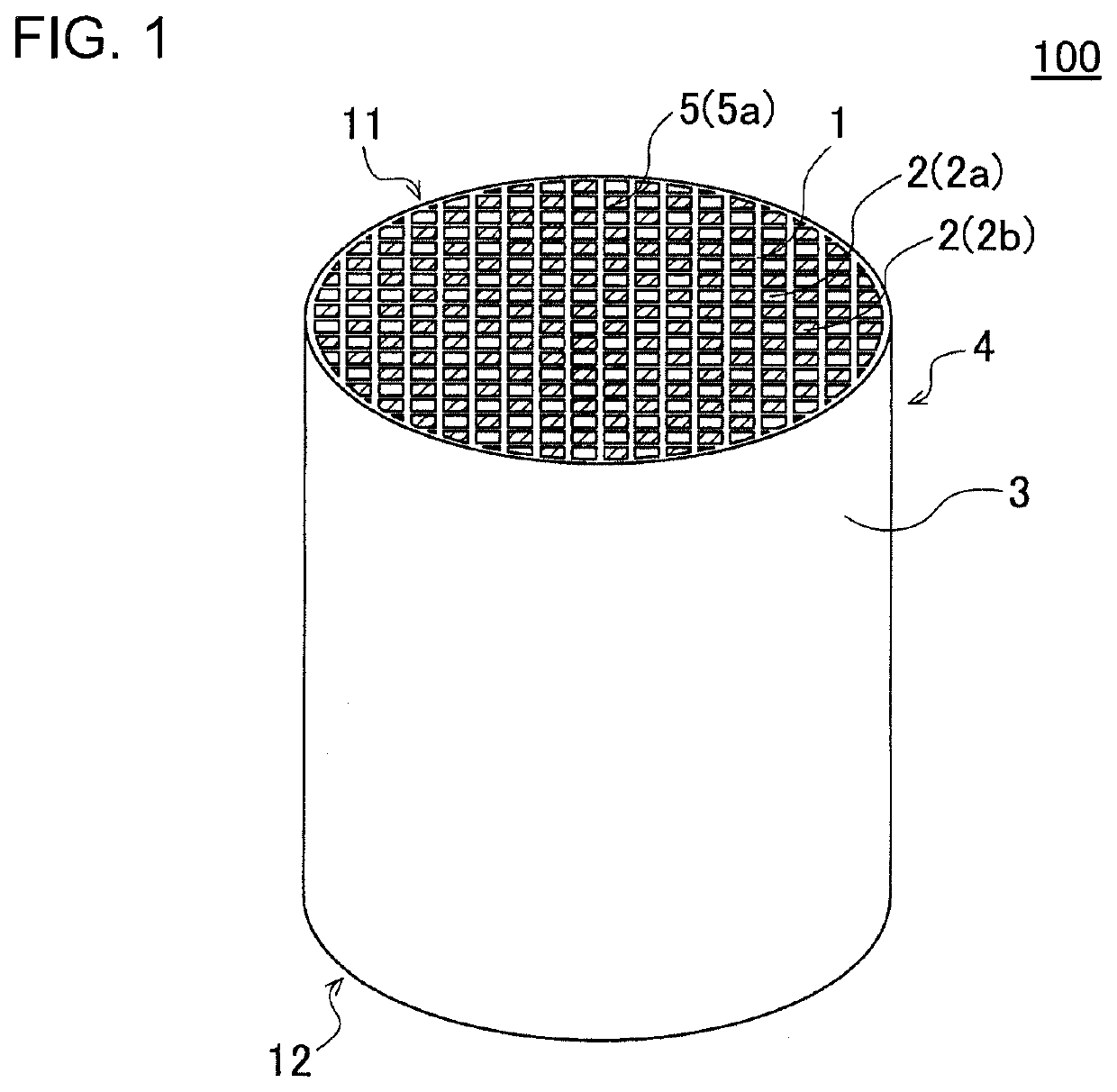
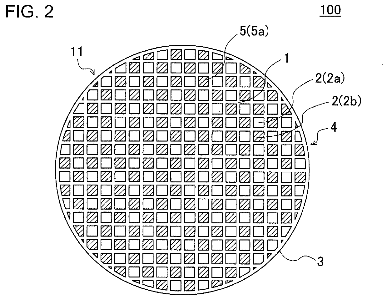
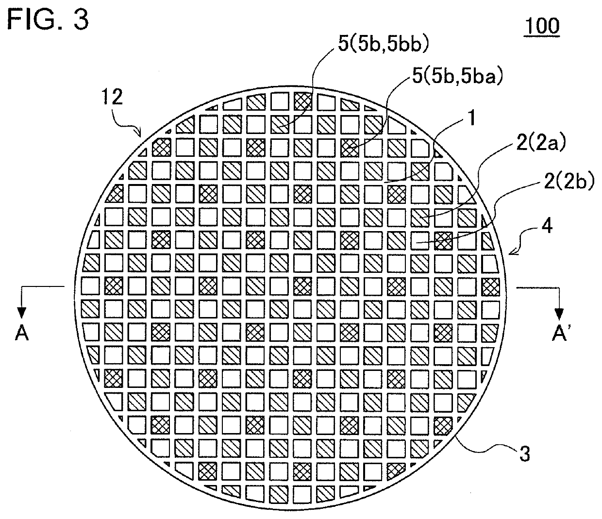
[0047]As shown in FIGS. 1 to 4, a first embodiment of the honeycomb filter of the present invention is a honeycomb filter 100 that includes a honeycomb structure 4 and a plugging portion 5. FIG. 1 is a perspective view schematically showing the first embodiment of a honeycomb filter of the present invention viewed from the inflow end face side. FIG. 2 is a plan view of the honeycomb filter of FIG. 1 viewed from the inflow end face side. FIG. 3 is a plan view of the honeycomb filter of FIG. 1 viewed from the outflow end face side. FIG. 4 is a schematic cross-sectional view taken along the line A-A′ of FIG. 3.
[0048]The honeycomb structure 4 has a pillar shape, and has a porous partition wall 1 that surrounds a plurality of cells 2. The plurality of cells 2 extends from the inflow end face 11 to the outflow end face 12 of the honeycomb structure 4 and serves as a through channel of fluid. In the honeycomb filter 100, the honeycomb structure 4 has ...
example 1
[0106]Materials of the honeycomb segments were the mixture of SiC powder and metal Si powder at the mass ratio of 80:20. Starch and foamable resin as the pore former were added, and methyl cellulose, hydroxypropoxyl methyl cellulose, surfactant and water were further added thereto, followed by kneading. In this way a kneaded material having plasticity was prepared.
[0107]Next, the prepared kneaded material was extruded, dried, fired, and then oxidized to obtain a prismatic columnar honeycomb segment. A protective layer was formed on the surface of this prismatic columnar honeycomb segment. Then, predetermined cells of the obtained prismatic columnar honeycomb segment were filled with slurry for plugging, and this was dried to obtain a plugged prismatic columnar honeycomb segment. An example of the method for forming the plugging portion is described below. Slurry for plugging is stored in a storage container. Next, a mask having openings at positions corresponding to the cells in whi...
examples 2 to 11
[0117]Honeycomb filters were manufactured similarly to the method of Example 1 other than that the structure of the first outflow side plugging portions and the second outflow side plugging portions was changed as shown in Table 1 or Table 2.
PUM
| Property | Measurement | Unit |
|---|---|---|
| Fraction | aaaaa | aaaaa |
| Fraction | aaaaa | aaaaa |
| Porosity | aaaaa | aaaaa |
Abstract
Description
Claims
Application Information