Fuel cell unit

Active Publication Date: 2018-05-31
TOYOTA JIDOSHA KK
View PDF0 Cites 1 Cited by
  • Summary
  • Abstract
  • Description
  • Claims
  • Application Information

AI Technical Summary

Benefits of technology

[0007]According to the above configuration, the fuel gas that is supplied to the fuel cell flows through the first gas channel, in which the amount of the pre

Problems solved by technology

For this reason, similar to the power generation cell, in the case where the fuel gas, which is supplied to the power generation cell, flows through the second gas channel in the pump cell, press

Method used


Image

  • Fuel cell unit
  • Fuel cell unit
  • Fuel cell unit

Examples


Example

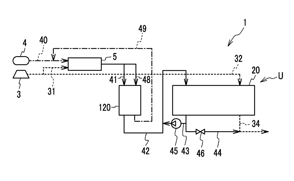
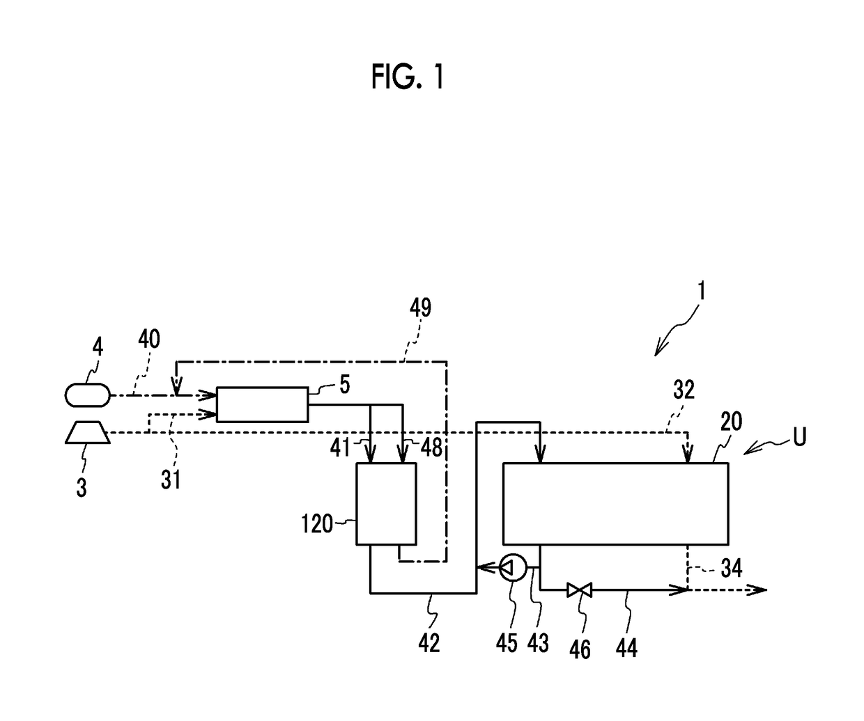
[0023]FIG. 1 is a configuration diagram of a fuel cell system 1. The fuel cell system 1 includes an air compressor 3, a fuel tank 4, a reformer 5, a fuel cell unit U, and the like. The fuel cell unit U includes a fuel cell 20 and an ammonia pump 120. The fuel cell 20 generates electricity when being supplied with oxidant gas and fuel gas. The ammonia pump 120 reduces an amount of ammonia in the fuel gas to be supplied to the fuel cell 20. The reformer 5 uses raw fuel and water to produce the fuel gas that contains hydrogen, and supplies the produced fuel gas to the fuel cell 20. The raw fuel is, for example, raw fuel containing hydrocarbons such as town gas, propane gas, naphtha, gasoline, and heating oil, or alcohol-based raw fuel such as methanol. When the reformer 5 reforms any of these types of the raw fuel, ammonia is possibly produced as a by-product, and the produced fuel gas contains ammonia. In addition, there is a case where liquid ammonia is used as the raw fuel. Also, in...


PUM


Abstract

A fuel cell unit includes: an ammonia pump including a pump cell that reduces an amount of ammonia in fuel gas; and a fuel cell including a power generation cell that is supplied with oxidant gas and the fuel gas. Each of the pump cell and the power generation cell has: a membrane electrode gas diffusion layer assembly; a first separator and a second separator; and a first gas channel and a second gas channel. In each of the pump cell and the power generation cell, the first gas channel and the second gas channel are formed such that an amount of pressure loss in the first gas channel is smaller than an amount of pressure loss in the second gas channel.

Description

INCORPORATION BY REFERENCE[0001]The disclosure of Japanese Patent Application No. 2016-231704 filed on Nov. 29, 2016 including the specification, drawings and abstract is incorporated herein by reference in its entirety.BACKGROUND1. Technical Field[0002]The present disclosure related to a fuel cell unit.2. Description of Related Art[0003]An ammonia pump that reduces an amount of ammonia in fuel gas has been known. The fuel gas, in which the amount of ammonia has been reduced, is supplied to a power generation cell of a fuel cell, and degradation of power generation performance by the power generation cell is thereby suppressed. Such an ammonia pump includes a pump cell in which a membrane electrode gas diffusion layer assembly is held by paired separators from both sides, and this pump cell has a similar structure to the power generation cell (for example, see Japanese Patent Application Publication No. 2008-27752 (JP 2008-27752 A)).SUMMARY[0004]In the power generation cell, oxidant...

Claims


Application Information

Patent Timeline
IPC IPC(8): H01M8/06H01M8/04186
CPCH01M8/06H01M8/04186H01M8/04089H01M8/04753H01M8/0662H01M8/0681Y02E60/50H01M8/04104H01M8/04746
Inventor MATSUSUE, MASAAKI
Owner TOYOTA JIDOSHA KK
Why Eureka
Try Eureka