
Ceramic porous body and method for producing the same, and dust collecting filter

Active Publication Date: 2019-10-03
NGK INSULATORS LTD
View PDF0 Cites 0 Cited by
  • Summary
  • Abstract
  • Description
  • Claims
  • Application Information

AI Technical Summary

Benefits of technology

The ceramic porous body in this patent has better strength and can handle higher temperatures without losing pressure. The method for producing it is also provided, along with a dust collecting filter.

Problems solved by technology

When the PMs are directly discharged into the atmosphere, environmental pollution is caused.
Further, the exhaust gas as stated above also contains harmful substances such as NOx, CO and HC.
This results in an increased pressure loss of the ceramic porous body and hence deteriorated function as a dust collection filter.
However, the conventional ceramic porous body has problems that, since it has low thermal conductivity, local heat generation occurs when the particulate matters deposited on the surface or inner side of the porous ceramic body is burned, and the particulate matters cannot be sufficiently removed.
However, the ceramic porous body disclosed in Patent Document 1 may not have good wettability between the binding material and the aggregate, and may lead to decreased strength and thermal conductivity as a result of a decreased contact area between the binding material and the aggregate.

Method used


Image

  • Ceramic porous body and method for producing the same, and dust collecting filter
  • Ceramic porous body and method for producing the same, and dust collecting filter
  • Ceramic porous body and method for producing the same, and dust collecting filter

Examples


embodiment 1

[0030]The porous ceramic body of the present embodiment includes: skeleton portions including an aggregate and a binding material; and pore portions formed between the skeleton portions and capable of allowing a fluid to flow therethrough.

[0031]Here, a pore diameter and a pore volume ratio of the pore portions are related to the pressure loss and the strength of the porous ceramic body. By increasing the pore volume ratio of the pores having a larger pore diameter, an increase in pressure loss can be suppressed, but the strength tends to be decreased. Therefore, the pore diameter and the pore volume ratio of the pore portions are required to be controlled so as to obtain a balance between the pressure loss and the strength of the ceramic porous body.

[0032]Therefore, in the ceramic porous body according to the present embodiment, the pore volume ratio of pores having a pore diameter of from 1 to 10 μm (hereinafter, which may be abbreviated as “pore volume ratio”) is controlled to be ...

embodiment 2

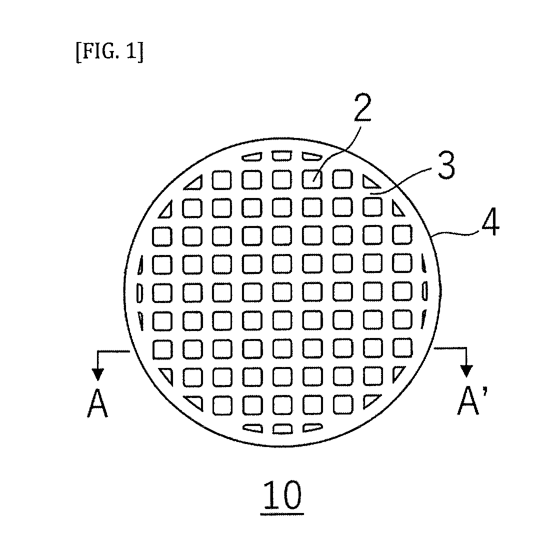
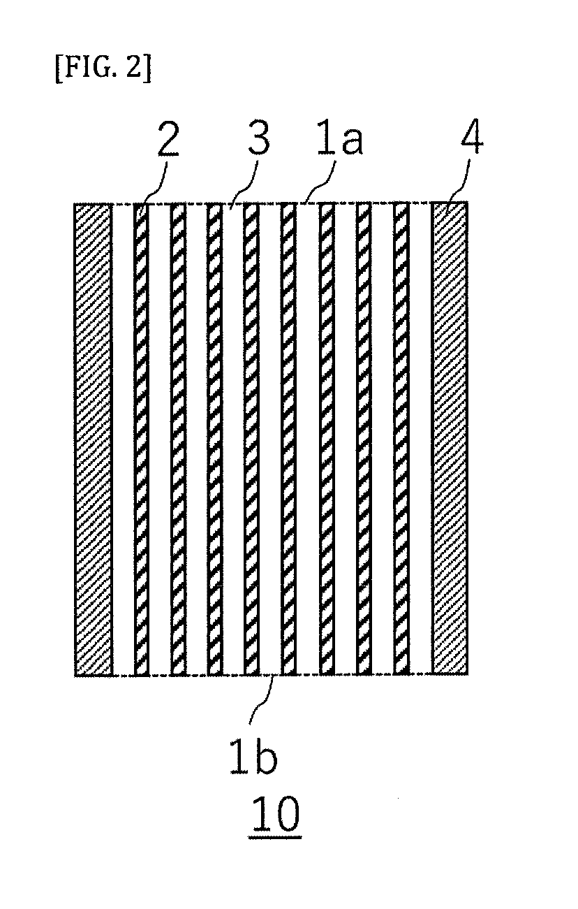
[0066]A porous ceramic body according to the present embodiment has a honeycomb structure in which a plurality of cells penetrating from a first end face to a second end face to form fluid flow paths are defined by partition walls. In the ceramic porous body having such a honeycomb structure, the partition walls correspond to the ceramic porous body. Further, in the ceramic porous body having the honeycomb structure, “a direction parallel to a flow direction of a fluid” refers to a direction orthogonal to a cell extending direction, and “a flow direction of a fluid” refers to a thickness direction of the partition wall.

[0067]The ceramic porous body according to the present embodiment is the same as the ceramic porous body of Embodiment 1, with the exception that the former has a predetermined honeycomb structure. Therefore, the descriptions of the configuration common to Embodiment 1 will be omitted here, and only portions different from those of Embodiment 1 will be described.

[0068...

embodiment 3

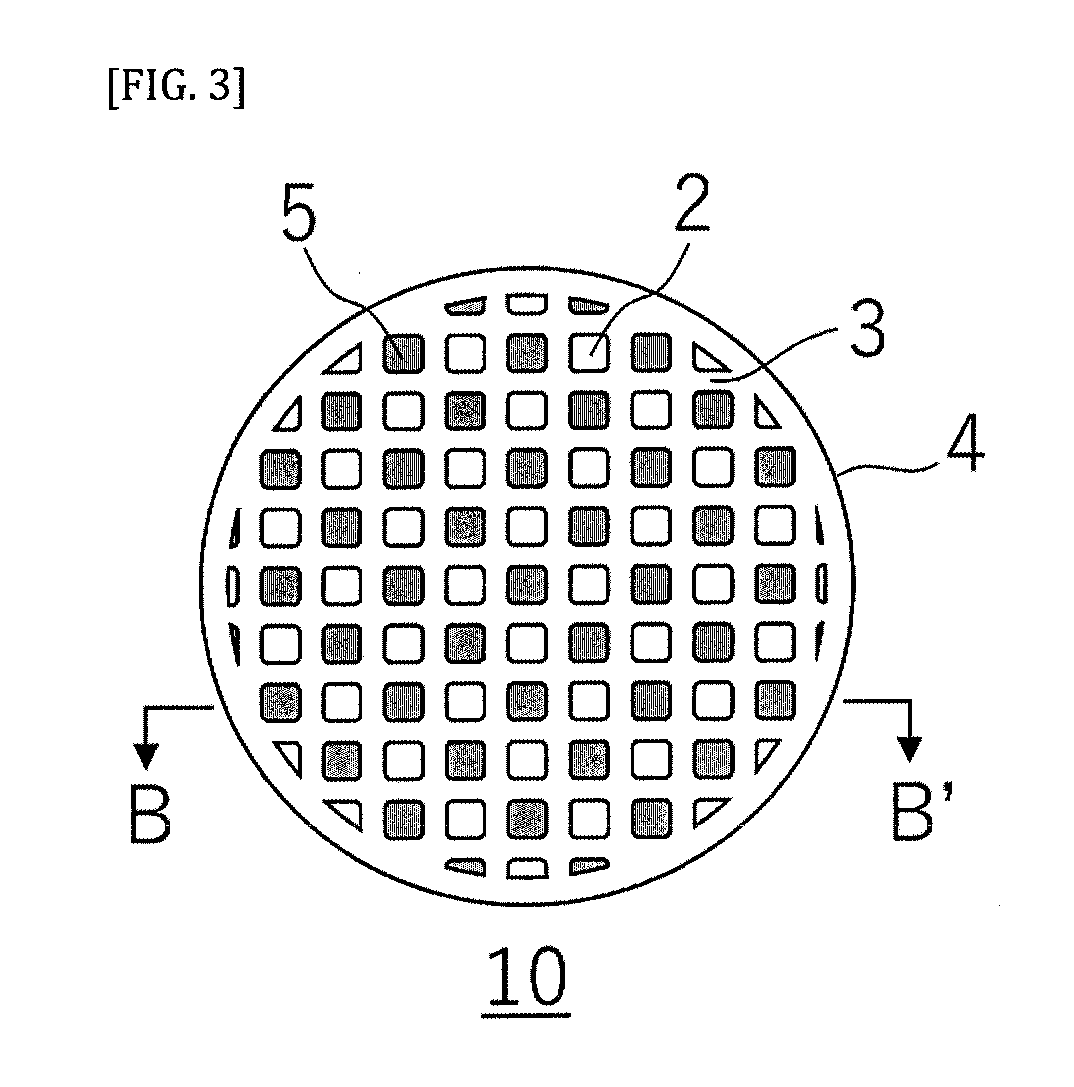
[0077]A ceramic porous body according to the present embodiment is different from the ceramic porous body according to Embodiment 2 in that the honeycomb structure of the former further includes opening portions of predetermined cells on the first end face and plugged portions provided at the opening portions of the remaining cells on the second end face. Therefore, descriptions of the configuration common to Embodiment 2 will be omitted herein, and only portions different from those of Embodiment 2 will be described.

[0078]FIG. 3 is a plan view of the ceramic porous body of the present embodiment as view from the first end face side. FIG. 4 is a cross-sectional view showing a cross section taken along the line B-B′ in FIG. 3.

[0079]As shown in FIGS. 3 and 4, the ceramic porous body 10 according to the present embodiment includes opening portions of predetermined cells 2 on a first end face 1a and plugged portions 5 provided at the opening portions of the remaining cells 2 on a second...


PUM

PropertyMeasurementUnit
Fractionaaaaaaaaaa
Fractionaaaaaaaaaa
Pore sizeaaaaaaaaaa

Abstract

A ceramic porous body comprising: skeleton portions including an aggregate and at least one binding material; and pore portions formed between the skeleton portions, the pore portions being capable of allowing a fluid to flow therethrough. In the ceramic porous body, the pore portions have a pore volume ratio of pores having a pore diameter of from 1 to 10 μm, of 45% or more, and a ratio of a contact area between the aggregate and the binding material to a surface area of the binding material of from 20 to 60%.

Description

[0001]This application claims the benefit under 35 USC § 119(a)-(d) of Japanese Application No. 2018-069311 filed Mar. 30, 2018, the entirety of which is incorporated herein by reference.FIELD OF THE INVENTION[0002]The present invention relates to a ceramic porous body and a method for producing the same, as well as a dust collecting filter.BACKGROUND OF THE INVENTION[0003]A large amount of particulate substances such as soot (hereinafter also referred to as “particulate matters” or “PMs”) is contained in exhaust gases discharged from internal combustion engines such as diesel engines and gasoline engines, and various combustion devices. When the PMs are directly discharged into the atmosphere, environmental pollution is caused. Therefore, an exhaust system for an exhaust gas is equipped with a dust collecting filter (hereinafter also referred to as “particulate filter”) for collecting the PMs. For example, the dust collecting filter used for purifying exhaust gases discharged from ...

Claims


Application Information

Patent Timeline
IPC IPC(8): C04B38/00B01D46/24
CPCB01D46/2429C04B38/0074C04B38/0054C04B38/0038B01D2046/2481C04B2111/00793C04B38/0009C04B2201/40B01D2046/2433C04B38/0006C04B35/565C04B35/622C04B35/6303C04B35/6365C04B35/638C04B35/64B01D39/2068C04B2235/9607C04B2235/6567B01D46/24492B01D46/24491C04B38/0051C04B2235/80C04B2235/3481C04B2235/3217C04B2235/77C04B2235/96C04B2235/661
Inventor NOGUCHI, HIROAKIICHIKAWA, SHUICHIKAWAKAMI, AKIFUMIITO, MITSUHIRO
Owner NGK INSULATORS LTD
Learn More