Honeycomb structure and exhaust gas purifying device

Pending Publication Date: 2021-12-16
NGK I
View PDF0 Cites 0 Cited by
  • Summary
  • Abstract
  • Description
  • Claims
  • Application Information

AI Technical Summary

Benefits of technology

[0008]However, as a result of studies, the present inventors have found that although when the technique disclosed in Patent Literature 1 is applied to a catalyst supported honeycomb or a honeycomb structure filter, a heating efficiency is increa

Problems solved by technology

However, as a result of studies, the present inventors have found that although when the technique disclosed in Patent Literature 1 is applied to a catalyst supported honeycomb or a honeycomb structure filter, a heating efficiency is increased as the number of cells into which a metal wire is inserted is increased, the number of cells that can be used as gas flow paths are reduced and areas of the fluid flow paths are r

Method used


Image

  • Honeycomb structure and exhaust gas purifying device
  • Honeycomb structure and exhaust gas purifying device
  • Honeycomb structure and exhaust gas purifying device

Examples


Example

[0029]Hereinafter, embodiments of a honeycomb structure according to the present invention will be described with reference to the drawing. However, the present invention is not limited to these embodiments, and various changes, modifications, and improvements may be made based on knowledge of those skilled in the art, without departing from the scope of the present invention.

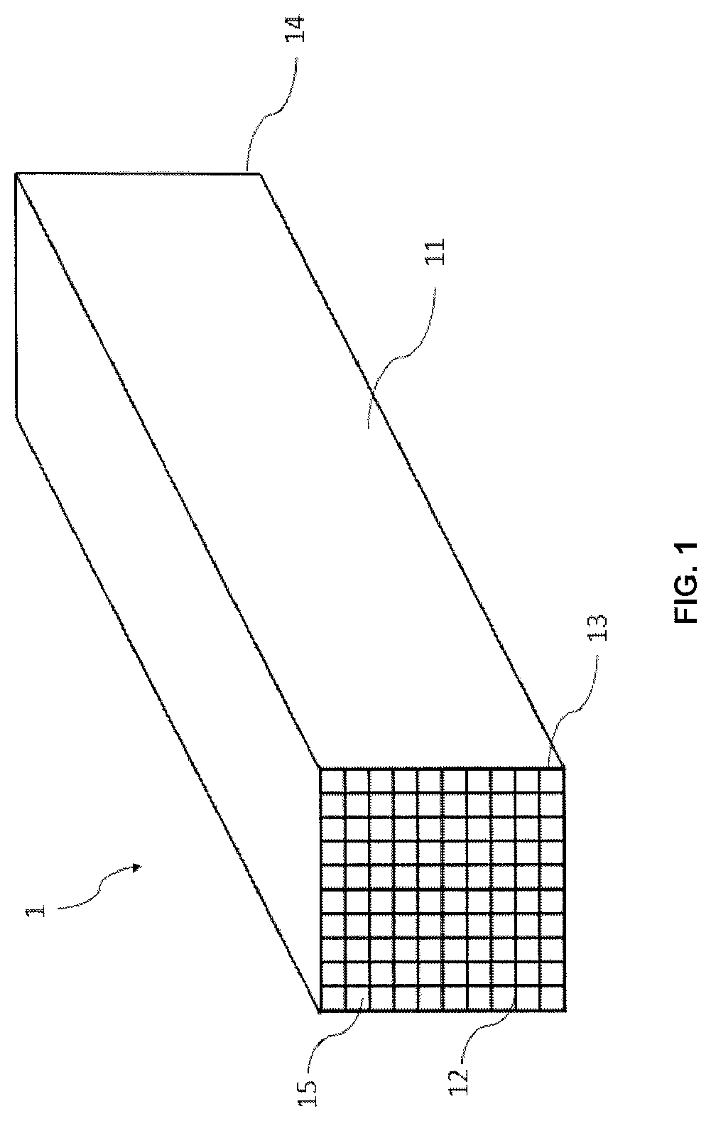
[0030]FIG. 1 is a perspective view schematically showing a honeycomb structure 1 according to an embodiment of the present invention. The illustrated honeycomb structure 1 is pillar-shaped and has an outer peripheral wall 11 located on the outermost circumference. Further, the illustrated honeycomb structure 1 has the porous partition walls 12 which are arranged inside the outer peripheral wall 11 and define a plurality of cells 15 that penetrate from one end face 13 to the other end face 14 to form flow paths.

[0031]Although materials of the partition walls 12 and the outer peripheral wall 11 of the honeycomb s...


PUM

PropertyMeasurementUnit
Temperatureaaaaaaaaaa
Pore sizeaaaaaaaaaa
Pore sizeaaaaaaaaaa

Abstract

A pillar shaped honeycomb structure, including: an outer peripheral wall; and a porous partition wall disposed inside the outer peripheral wall, the a porous partition wall defining a plurality of cells, each of the cells extending from one end face to other end face to form a flow path, wherein a surface of the porous partition wall in the cells comprise a collecting layer having an average pore diameter lower than that of the porous partition wall; and wherein magnetic particles having a Curie point of 700° C. or higher are provided either or both between the surfaces of the porous partition wall and the collecting layer, and on the collecting layer.

Description

FIELD OF THE INVENTION[0001]The present invention relates to a honeycomb structure and an exhaust gas purifying device. More particularly, the present invention relates to a honeycomb structure and an exhaust gas purifying device, which have an improved combustion efficiency of carbon particulates and the like due to induction heating and have a suppressed increase in pressure loss.BACKGROUND OF THE INVENTION[0002]There is an increased need for reduction of harmful components (HC, NOx, CO) in automobile exhaust gas. At present, the harmful components to be discharged are discharged during a period immediately after starting an engine, i.e., a period during which a catalyst temperature is lower and an activity of the catalyst is insufficient. To address this problem, Patent Literature 1 discloses a technique for inserting a magnetic wire into a part of cells of a cordierite honeycomb which is widely used as a catalyst supported honeycomb, and passing an electric current through a coi...

Claims


Application Information

Patent Timeline
IPC IPC(8): F01N3/28C04B38/00B01D46/24B01D39/20B01D53/94
CPCF01N3/2828F01N2370/02C04B38/0096C04B38/0058C04B38/0054B01D46/248B01D46/2429B01D46/24492B01D46/2482B01D46/2474B01D46/24494B01D46/24491B01D39/2068B01D53/94B01D2255/9155F01N2330/06C04B38/0006B01D46/00B01J35/04C04B41/85C04B41/89F01N3/035C04B38/0009C04B2111/00793C04B2111/0081B01D2255/9022B01D2255/9025B01D2259/814B01D46/2422F01N3/2013F01N3/0222F01N2510/0684B01D2239/0478Y02T10/12C04B35/00C04B38/0012
Inventor KIMATA, TAKAFUMIMIYAIRI, YUKIOMASUDA, MASAAKIHOSODA, KAZUYA
Owner NGK I
Why Eureka
Try Eureka