Flow path device and droplet forming method

Inactive Publication Date: 2019-02-28
KOBE STEEL LTD
View PDF9 Cites 0 Cited by
  • Summary
  • Abstract
  • Description
  • Claims
  • Application Information

AI Technical Summary

Benefits of technology

[0010]An object of the present invention is to provide a flow path device and a droplet forming method capable of forming both an aqueous and an oleaginous droplets without requiring front surface treatme

Problems solved by technology

In a case where the wettability of an inner wall surface of the channel is reformed by surface treatment of the inner wall surface, the aqueous or oleaginous property of the formable droplets does not receive limitation in accordance with the property of the base material, but work for the surface treatment of the inne

Method used

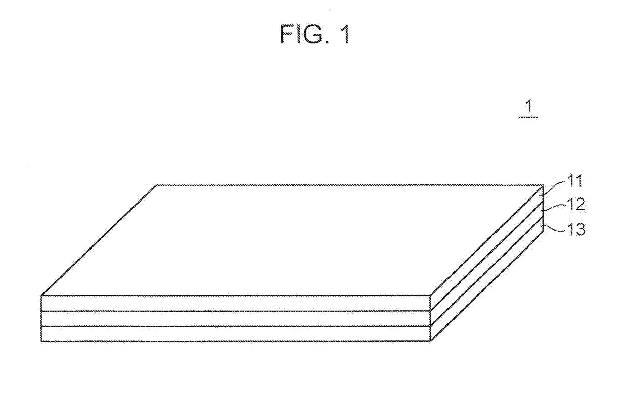
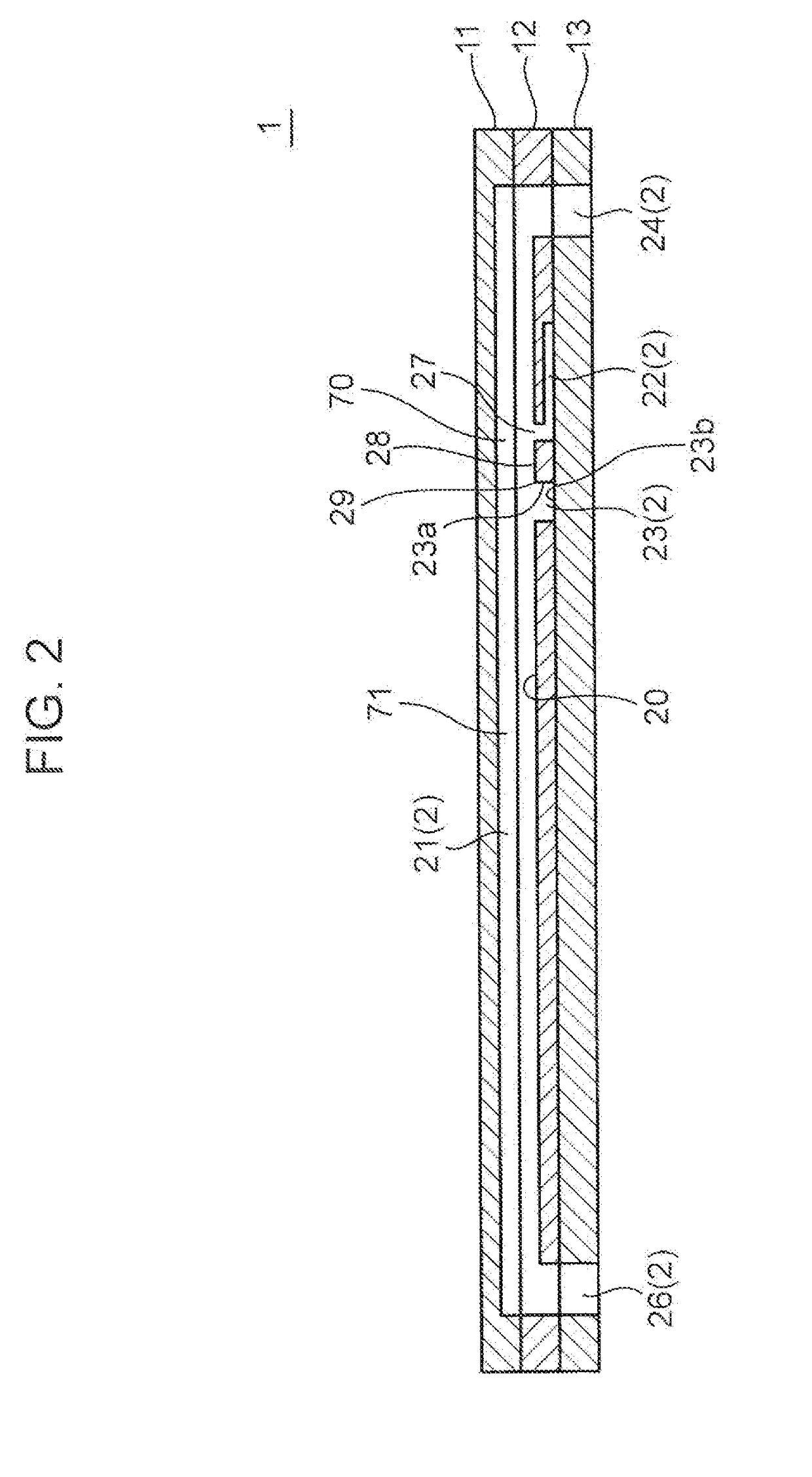
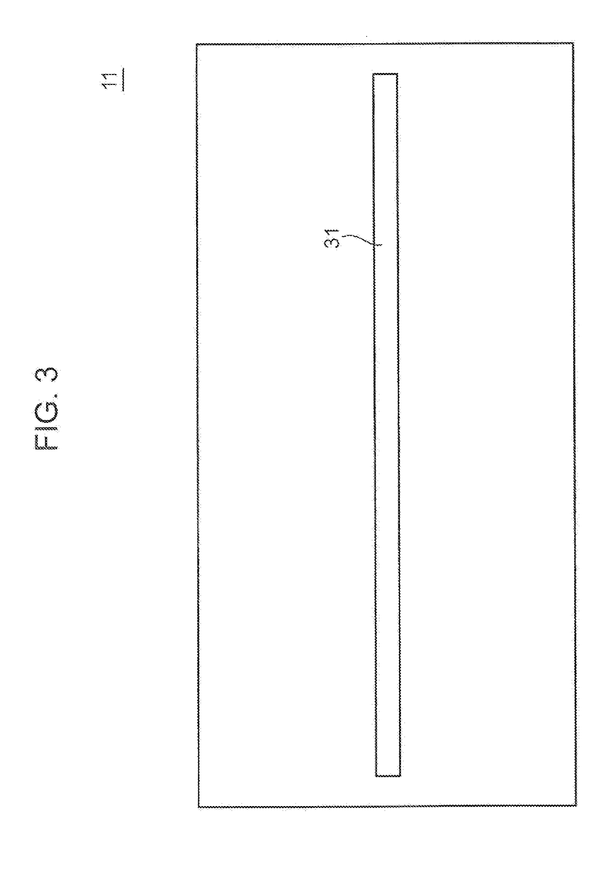

Image

  • Flow path device and droplet forming method
  • Flow path device and droplet forming method
  • Flow path device and droplet forming method

Examples


embodiment

SUMMARY OF EMBODIMENT AND MODIFICATION

[0103]The above embodiment and the above modifications are summarized as follows.

[0104]The flow path device according to each of the above embodiment and the above modifications is a flow path device having, internally, at least one channel allowing a continuous phase liquid and a dispersed phase liquid to flow so as to form a dispersed phase droplet in the continuous phase liquid, wherein the channel has a main channel which allows flow of the continuous phase liquid, and an auxiliary channel which is connected to a predetermined portion of the main channel to guide the dispersed phase liquid to the main channel, the predetermined portion being a portion between both ends of the main channel, the flow path device has an inner wall surface which encloses the main channel to define the main channel, the main channel has a connecting port formed in the inner wall surface and communicated with the auxiliary channel, and the inner wall surface has a...


PUM

PropertyMeasurementUnit
Flow rateaaaaaaaaaa
Areaaaaaaaaaaa

Abstract

A flow path device has at least one channel. The channel has a main channel which allows flow of a continuous phase liquid, and an auxiliary channel which is connected to a predetermined portion of the main channel. The flow path device has an inner wall surface which encloses the main channel. The main channel has a connecting port formed in the inner wall surface and communicated with the auxiliary channel, and the inner wall surface has an enlarged surface provided at a position on a downstream side of the connecting port, and the enlarged surface spreads to outside of the main channel so as to promote removal of the dispersed phase liquid from the inner wall surface, the dispersed phase liquid being adhered to the inner wall surface in consequence of flowing from the auxiliary channel into the main channel through the connecting port.

Description

TECHNICAL FIELD[0001]The present invention relates to a flow path device and a droplet forming method.BACKGROUND ART[0002]Conventionally, a flow path device including a channel allowing a continuous phase and a dispersed phase to flow so as to form dispersed phase droplets in the continuous phase is known. The following Patent Literatures 1 and 2 each illustrate an example of such a flow path device.[0003]A flow path device disclosed in the following Patent Literature 1 includes a plurality of microchannels disposed so as to intersect with each other, and connected to each other. In this flow path device, a dispersed phase joined from one of the microchannels to a continuous phase flowing in the other microchannel, and dispersed phase droplets are formed in the continuous phase at the joining portion. This Patent Literature 1 discloses that in a case where a base material forming the microchannels is made of acryl, oil is used for the continuous phase, and water is used for the disp...

Claims


Application Information

Patent Timeline
IPC IPC(8): B01F3/08B01J13/14B01J19/00B01F5/00
CPCB01F3/0803B01F3/0807B01J13/14B01J19/0093B01F5/0057B01J2219/00599B01J2219/00889B01J19/00B01F23/41B01F25/3141B01F25/4337B01F33/30B01F33/813B01J13/02B01F23/40B01F25/00B01F23/405B01F25/10
Inventor MATSUOKA, AKIRANOISHIKI, KOJIOZONO, TOMOHIRO
Owner KOBE STEEL LTD
Why Eureka
Try Eureka