Proximity detector for night vision goggles shut-off

a technology of proximity detector and night vision goggles, which is applied in the direction of pulse technique, instruments, and reradiation, can solve the problem of rendering the nvg inoperable at an inopportune tim

Active Publication Date: 2007-12-06
ELBIT SYSTEMS OF AMERICA LLC
View PDF26 Cites 24 Cited by
  • Summary
  • Abstract
  • Description
  • Claims
  • Application Information

AI Technical Summary

Problems solved by technology

However, problems exist with this technology.
When the soldier is not looking in a level direction, but is looking up or down, the magnet may inadvertently slide to the “OFF” position, rendering the NVG inoperable at an inopportune time.
Further, the magnet slides within its housing with an audible “click” that may disturb soldiers fearful of generating any sound whatsoever that may give away their position to the enemy.

Method used


Image

  • Proximity detector for night vision goggles shut-off
  • Proximity detector for night vision goggles shut-off
  • Proximity detector for night vision goggles shut-off

Examples


Embodiment Construction

[0015] Certain terminology is used herein for convenience only and is not to be taken as a limitation on the present invention. The terminology includes the words specifically mentioned, derivatives thereof and words of similar import. As used herein, the term “rear” is defined to mean a direction closer to a user when the night vision device is in a use position as described herein and “front” is defined to mean a direction farther from a user when the night vision device is in a use position as described herein. The following describes preferred embodiments of the invention. However, it should be understood based on this disclosure, that the invention is not limited by the preferred embodiments of the invention.

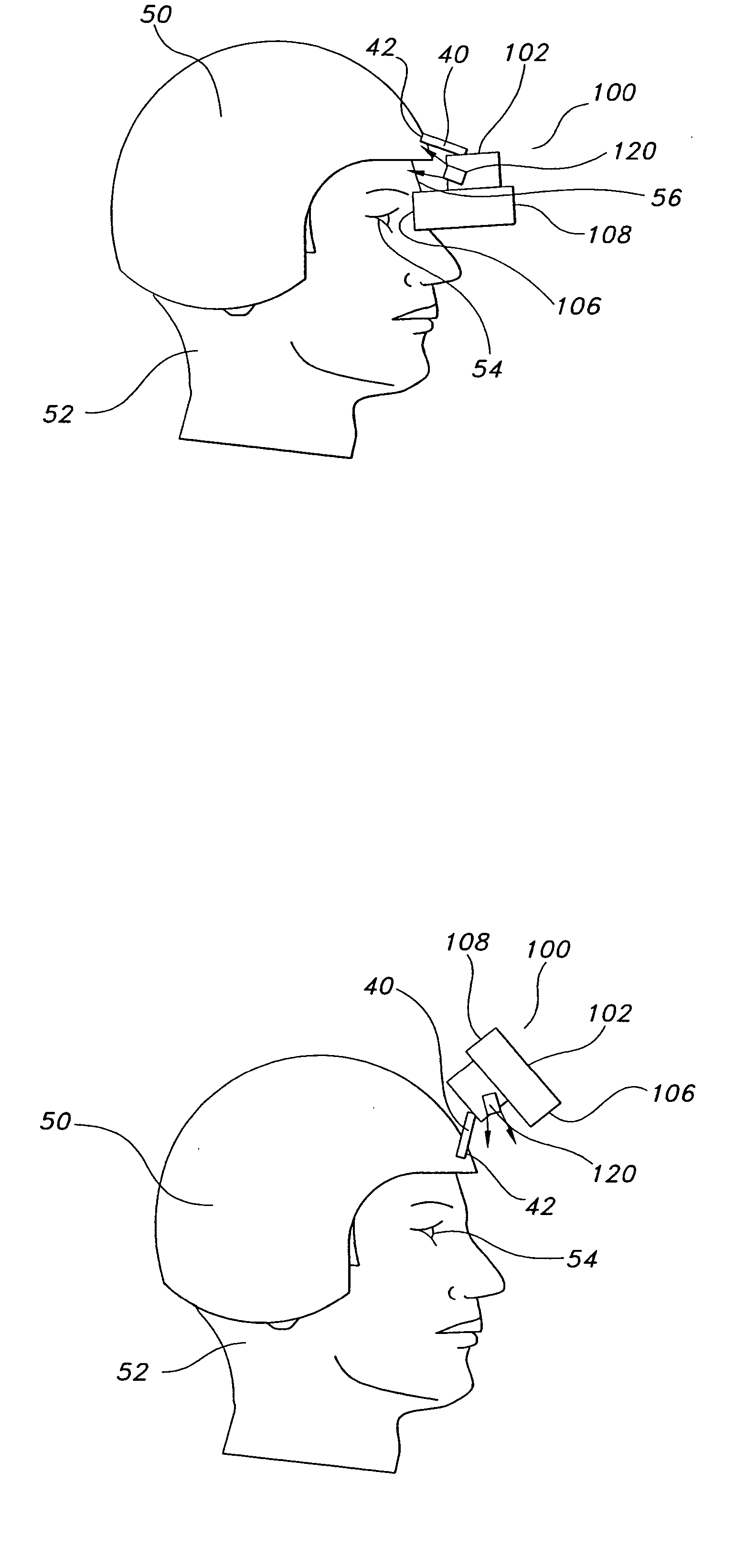
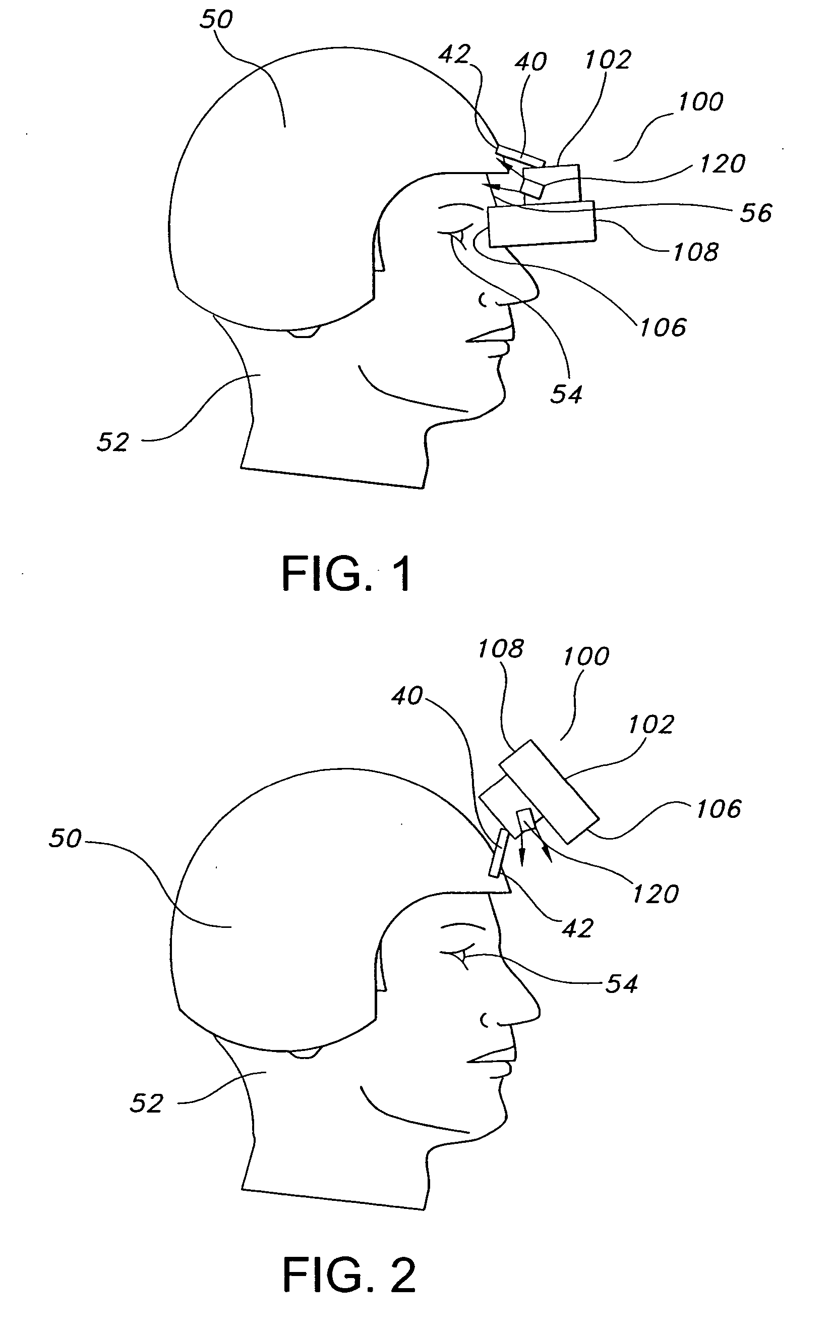
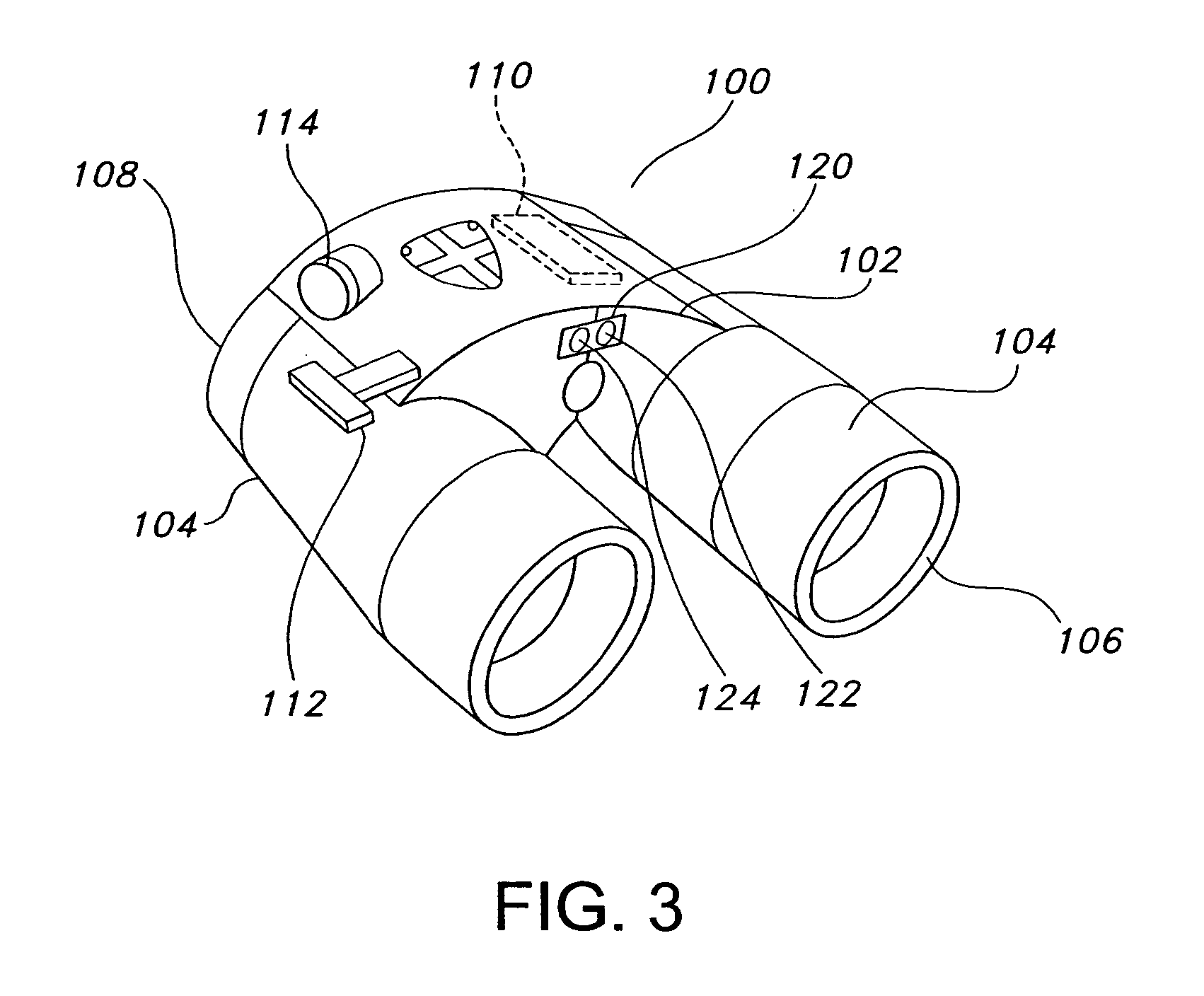
[0016] Referring to the figures in general, a night vision device according to the several embodiments of the present invention is disclosed. The device includes a proximity sensor comprised of an infrared emitter and detector assembly that is used to detect when the night...


PUM


Abstract

A night vision device is disclosed. The device includes a housing that houses an intensifier tube and a proximity sensor mounted on the housing. An ON / OFF switch is operatively coupled to the intensifier tube and to the proximity sensor such that operation of the ON / OFF switch to the “ON” position automatically activates the proximity sensor. A method of operating the night vision device with the proximity sensor is also disclosed.

Description

BACKGROUND OF THE INVENTION [0001] Night vision devices, such as night vision goggles (NVG's) are well known for being able to enable a user of such a device to easily see in darkened environments. These devices are often used in military applications to enable soldiers to see without the use of extraneous visible lighting, such as flashlights, which may give away their position to the enemy. The NVG intensifies the available low-level ambient light, and provides an image having a generally greenish glow that enables the user to see his surroundings. [0002] The NVG is often mounted on a soldier's helmet and is movable between an operational position in front of the soldier's eyes, and a stowed position, such as above the soldier's eyes. However, in the stowed position, the eyepieces are generally directed outward, away from the soldier, and it may be possible for an enemy to see the green glow from the eyepieces, thus giving away the soldier's position. [0003] To counter this proble...

Claims


Application Information

Patent Timeline
Patent Type & Authority Applications(United States)
IPC IPC(8): G08B21/00H01J31/49G01S17/04
CPCG01S17/026H03K17/9631H03K17/941G02B23/125G01S17/04G02B23/12
Inventor SMITH, WILLIAM A.OESTERREICH, MARK E.
Owner ELBIT SYSTEMS OF AMERICA LLC
Why Eureka
Try Eureka