
Candle holder and flame extinguisher device

a candle and flame extinguisher technology, applied in the direction of capillary burners, combustion types, lighting and heating apparatuses, etc., can solve the problems of numerous problems, problematic assumptions, and obvious safety hazards of burning candles,

Active Publication Date: 2007-12-27
ECLIPSE HOME DECOR
View PDF8 Cites 5 Cited by
  • Summary
  • Abstract
  • Description
  • Claims
  • Application Information

AI Technical Summary

Benefits of technology

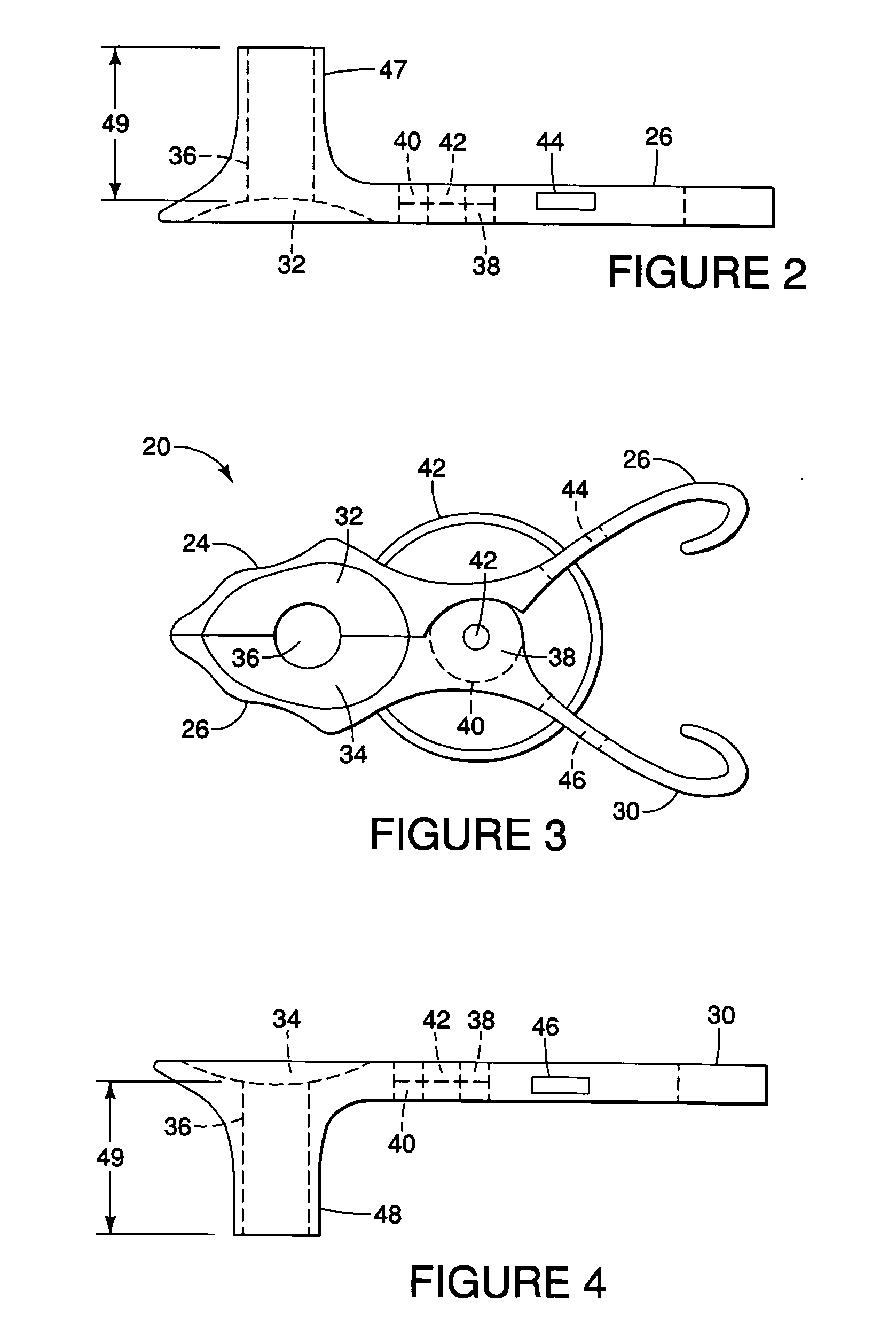
[0007]The embodiments of the present invention also regulate the burning of a candle using a passive extinguisher that requires no mechanical parts or human intervention. A hole in the holding device is formed in the bowl when the two movable parts are closed. Each movable part forms half of the bowl and therefore half of the hole. Underneath the holding device, when the clamp is oriented properly with the top, bowl-side facing away from the ground, the hole is formed out of a both halves of a cylindrical extension on each part of the holding device. The extension is formed as a nearly-straight hollow cylinder away from the device's bowl area. When the holding device is opened, the cylindrical extension halves open in two at which time they may be positioned on either side of a candle and then closed, thereby securing the candle inside the cylindrical extension. When the candle burns down inside extension, the lack of adequate oxygen in the enclosed space to fuel the burning wick causes the flame to extinguish.

Problems solved by technology

Burning a candle presents an obviously safety hazard.
The flame may overheat more wax than is needed to burn and cause the liquid hot wax to drip down from the top of the candle.
If the dripping wax caught fire or if the candle tipped over indoors, a potential house fire could result.
However, these types of devices are subject to numerous problems and problematic assumptions.
Spring-loaded clamps are assumed to work but may or may not close and cut the wick properly.
The candle may burn lop-sided that either holds the mechanism open too long for the cutting part to properly extinguish the flame or will not allow a device to lower adequately and snuff out the flame.
However, the prior devices create a potential fire hazard by not providing a passive candle extinguisher that provides an adequate enclosure around a burning candle so when the candle burns down, the flame is deprived of oxygen and extinguishes.
When the candle burns down inside extension, the lack of adequate oxygen in the enclosed space to fuel the burning wick causes the flame to extinguish.

Method used


Image

  • Candle holder and flame extinguisher device
  • Candle holder and flame extinguisher device
  • Candle holder and flame extinguisher device

Examples


Embodiment Construction

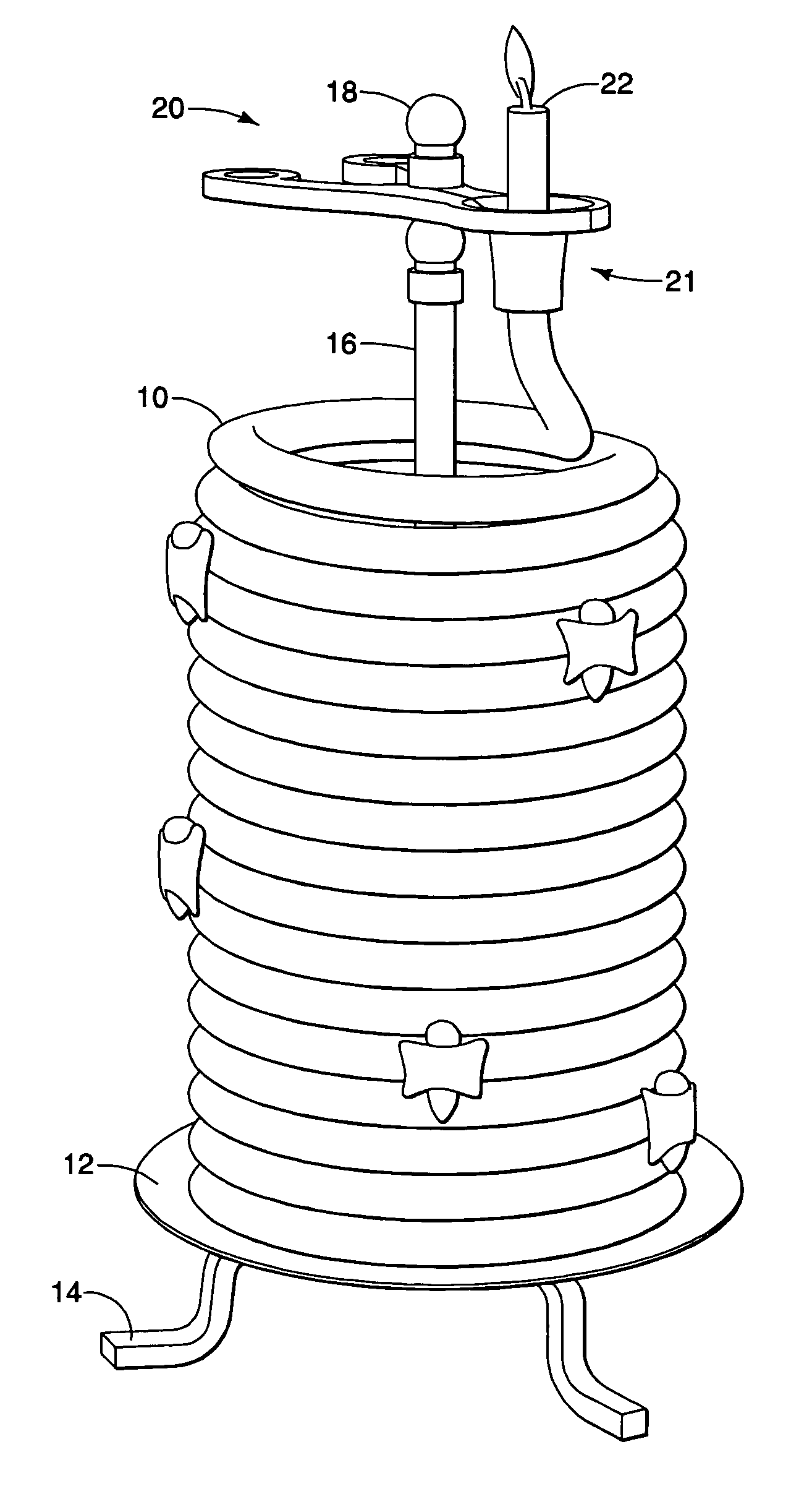
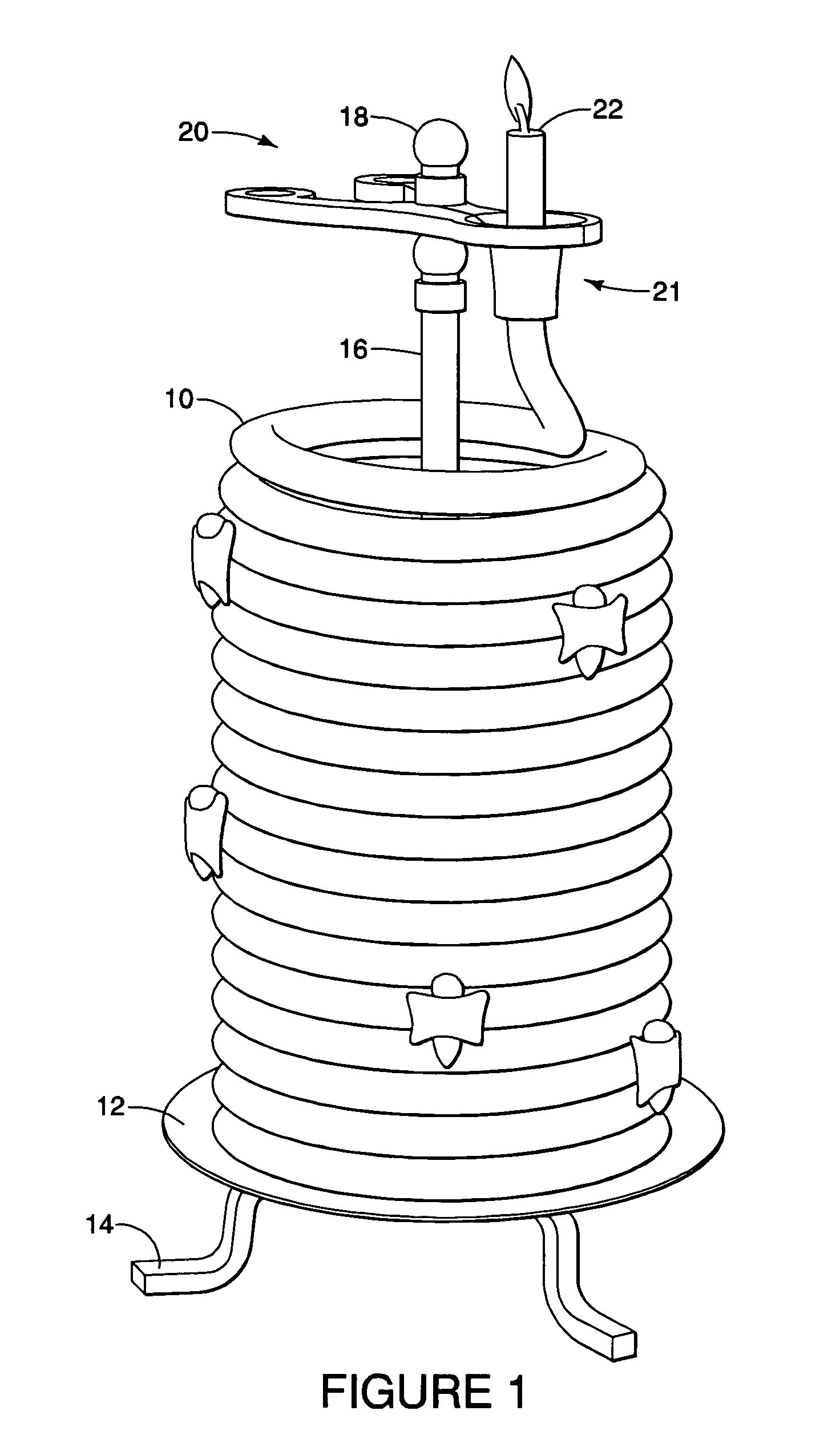
[0017]Referring to FIG. 1, the preferred embodiment of a candle holder 20 with a passive flame extinguisher is illustrated while mounted on a stand. A candle 10 is coiled upon a base 12 that is elevated from a surface by a plurality of legs 14 attached to the base 12. A rod 16 is attached to base 12 and rises vertically such that it remains in-place with adequate rigidity and strength to support holder 20. Candle 10 is cylindrically shaped but flexible to allow it to coil around rod 16 and stack up vertically upon itself. Candle holder device 20 is attached to rod 16, near the end distal to base 12, and held in place by cap 18. Candle holder 20 is preferably attached so that it is supported underneath the holder on the rod, to prevent the holder 20 from dropping down the rod, and allows holder 20 to support and end of candle 10. The holder 20 should swivel around rod 16 to provide rotational adjustment when drawing candle 10 up from the base 12.

[0018]FIG. 3 shows an elevation plan o...


PUM


Abstract

A device to regulate the burning of a candle is provided using a passive extinguisher that requires no mechanical parts or human intervention. The device is formed as tongs that form, when closed, a hollow cylindrical extension that can securely hold a burning candle. When the burning candle burns into the cylindrical extension, the flame is extinguished by operation of oxygen deprivation.

Description

FIELD OF THE INVENTION[0001]The present invention relates to a device for holding a candle that extinguishes a burning wick without mechanical or human interactionBACKGROUND OF THE INVENTION[0002]Burning a candle presents an obviously safety hazard. Candles have an open flame burning from a wick and melted wax. The flame may overheat more wax than is needed to burn and cause the liquid hot wax to drip down from the top of the candle. If the dripping wax caught fire or if the candle tipped over indoors, a potential house fire could result.[0003]Technology to improve the utilitarian aspects of burning a candle include various devices for holding a candle and automatically extinguishing the flame using mechanical means. Some devices attempt to automatically regulate the burning of a candle by using clamps or sharp edges, combined a moving or spring-loaded mechanism to cut off the burning wick when the wax candle burns down to a pre-set level. Some may snuff out the candle from lowering...

Claims


Application Information

Patent Timeline
Patent Type & Authority Applications(United States)
IPC IPC(8): F23N5/00
CPCC11C5/006F23Q25/00F23D3/26F23D3/16
Inventor VIGGIANI, ANTHONY
Owner ECLIPSE HOME DECOR
Learn More