
Footwear having a rigid shell

a technology of rigid shells and boots, applied in the field of boots, can solve the problems of loss of precision in steering the ski, affecting the perception of biases of seasoned skiers, and affecting the performance of the ski

Active Publication Date: 2008-01-03
SALOMON SA
View PDF21 Cites 21 Cited by
  • Summary
  • Abstract
  • Description
  • Claims
  • Application Information

AI Technical Summary

Benefits of technology

[0021] The article of footwear of the invention includes a shell or a shell element made of a rigid plastic base material whose softening point is greater than 170° C. At least in a local portion of the shell or shell element of the article ...

Problems solved by technology

However, feet have complex shapes that vary from one person to another, so shells and linings are typically manufactured to fit a range of differently shaped feet.
Too much pressure can hinder how a seasoned skier perceives biases / pressures and can give a recreational skier, i.e., a less-seasoned skier, a feeling of discomfort, which, in the long run, can tend to develop into a feeling of pain.
Conversely, the foot must not be loose in the liner caused by empty space(s) between the foot and the liner or between the shell and the liner, which results in a loss of precision in steering the ski.
These techniques yield good results, but their range of application is limited because the deformation of the liner is limited by the thickness of the liner wall and the inner volume of the shell.
However, deforming a shell requires locally heating the wall at high temperature as well as the use of a heavy equipment, such as a 500° C. hot-air blower, stirrup, and hydraulic piston, which are inserted in the shell to exert a pushing force against its walls, thereby resulting in a lack of precision in terms of localization and amplitude of deformation because one works on the bare shell.
A deterioration of the outer appearance of a boot in the zones which have been heated can also result.
These methods of manufacture yield good results, but are not entirely satisfactory.
The shell is not clearly deformed and there is, therefore, no substantial improvement in comfort for a foot that would be too greatly pressured by the liner.

Method used


Image

  • Footwear having a rigid shell
  • Footwear having a rigid shell
  • Footwear having a rigid shell

Examples


Embodiment Construction

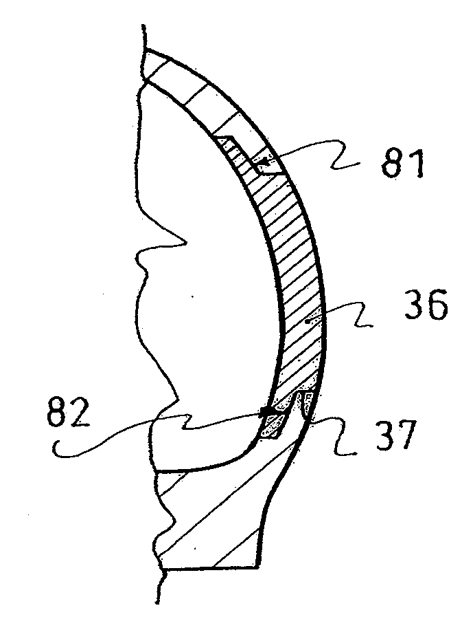
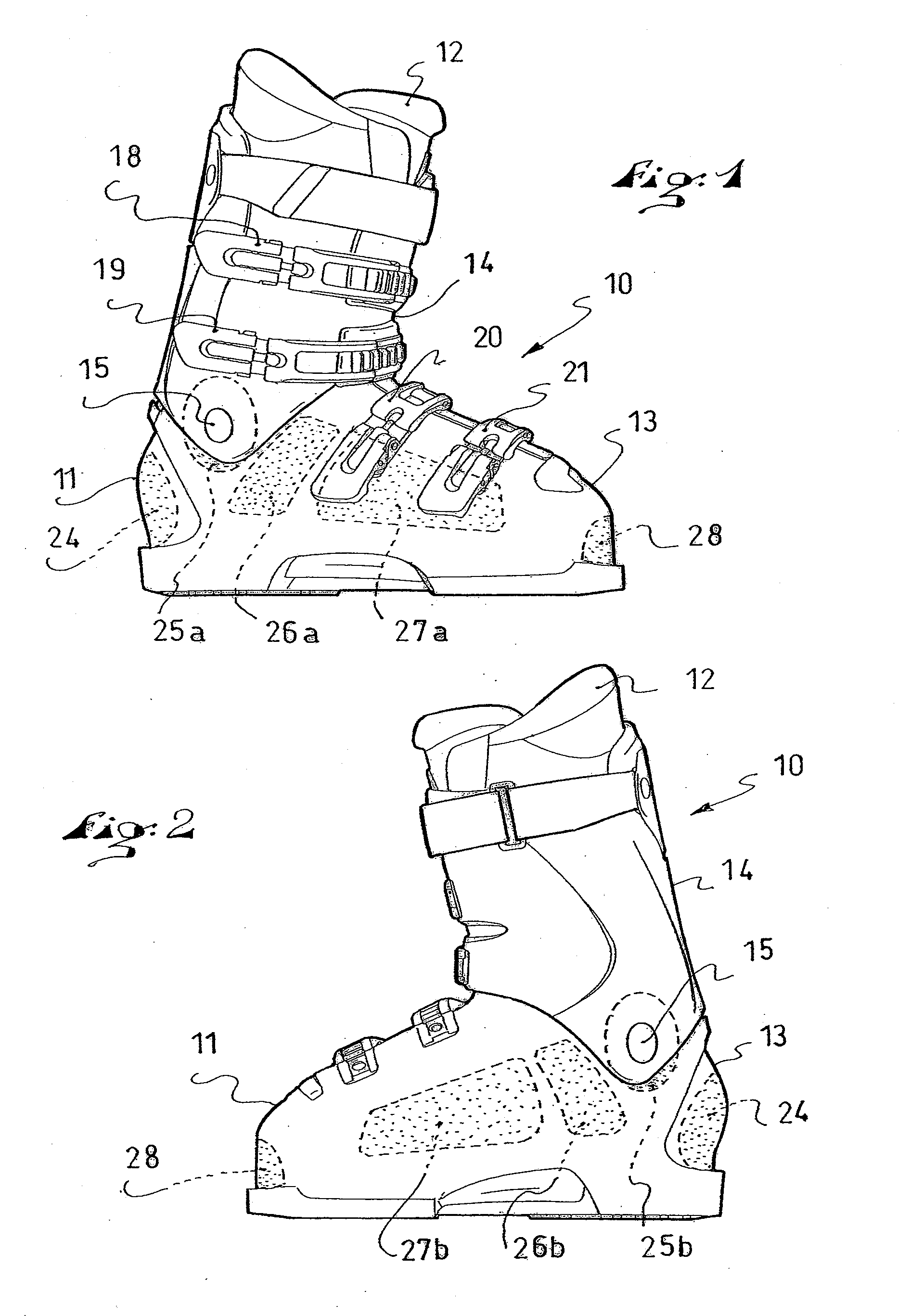
[0031]FIGS. 1 and 2 illustrate an article of footwear 10. More particularly, in the example shown, the article of footwear is a ski boot. Another type of footwear could be shown, such as a snowboard boot, a trail-running shoe provided with a shell, or a shoe or boot having a portion of the upper including a rigid element (such as a stiffener, a collar, etc). The boot conventionally includes a shell 11 and a comfort liner 12 provided to envelop a user's foot. The shell includes a shell base 13 surmounted by a collar 14. The collar is connected to the shell base via an articulation 15 located approximately in the area of the malleolus. On top of the shell base and at the forefront of the collar, the shell has two flaps, which can be moved apart from one another to widen the shell's opening when the foot is inserted into the boot, and which can be moved closer together to overlap when closing the boot.

[0032] The liner 12 is of any appropriate type. It is, for example, made of foam wit...


PUM


Abstract

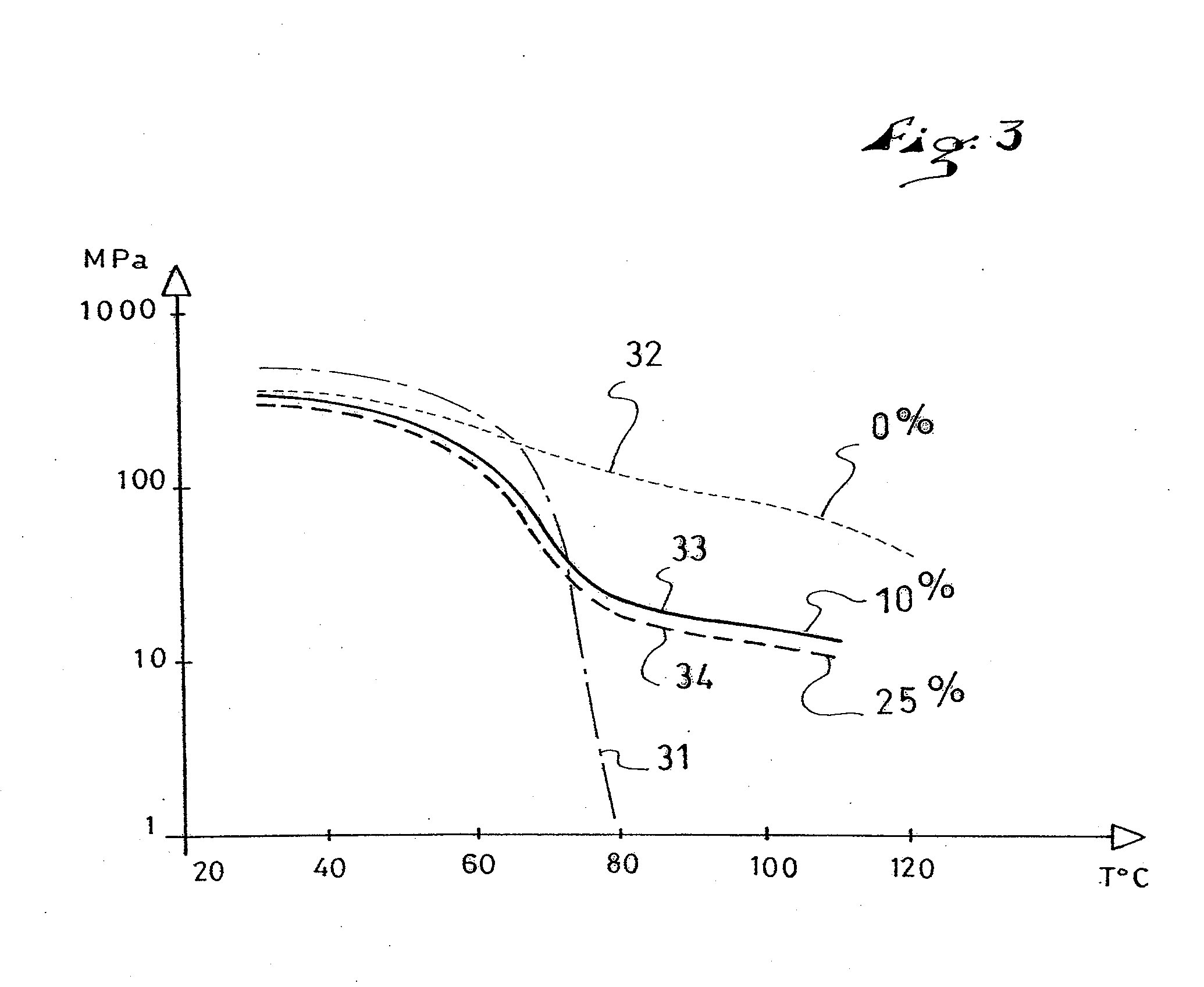
Footwear, such as a sports boot, including a shell or a shell element made of a rigid plastic base material whose softening point is greater than 170° C. and a method of manufacturing such footwear. At least in one local portion of the shell or shell element, the base material of the shell includes an additive having a melting temperature lower than 100° C., in a proportion of between 3% and 45% in a first embodiment and between 10% and 25% in a second embodiment. A heating machine includes a base provided to receive at least one boot along a longitudinal direction defined by the sole and a hot air blower. The heating machine includes at least two air blowing channels facing one another and located on each side of the longitudinal direction.

Description

CROSS-REFERENCE TO RELATED APPLICATION [0001] This application claims priority under 35 U.S.C. §119 of French Patent Application No. 06.05825, filed on Jun. 28, 2006, the disclosure of which is hereby incorporated by reference thereto in its entirety. BACKGROUND OF THE INVENTION [0002] 1. Field of the Invention [0003] The invention relates to footwear, such as shoes or boots, such as sports footwear in particular, which include a rigid shell. The invention also relates, albeit non-exclusively, to the field of gliding sports, such as skiing, for example. The invention also relates to other types of footwear having a rigid shell, such as trail-running shoes or footwear the upper of which includes a rigid element, such as a stiffener, a collar, or other part. The invention also relates to a pair of shoes or boots, a heating machine for shaping the shoes or boots, and a method for manufacturing footwear. [0004] 2. Description of Background and Other Information [0005] In a known manner,...

Claims


Application Information

Patent Timeline
IPC IPC(8): A43B5/04B29D35/00
CPCA43B3/26A43B5/04A43B5/0427A47L23/205A43D3/1408A43D95/10A43B5/0482
Inventor CHALLANDE, CHRISTIAN
Owner SALOMON SA
Learn More