Intake structure of water bag

Active Publication Date: 2008-01-03
WANG LO PIN
View PDF7 Cites 3 Cited by
  • Summary
  • Abstract
  • Description
  • Claims
  • Application Information

AI Technical Summary

Benefits of technology

[0006]According to the objective of the present invention, a water bag includes a soft bag with an intake, a lid detachably covering the intake of the bag, a hose having en end connected to the bag and a mouthpiece connected to a free end of the hose. The hose has a water inlet to inject water into the soft bag and a cap detachably covering the water inlet. Therefore, water may be injected through the water inlet directly without having to take the soft bag out of the backpack.

Problems solved by technology

The refill action of the conventional water bag is inconvenient to user.

Method used


Image

  • Intake structure of water bag
  • Intake structure of water bag
  • Intake structure of water bag

Examples


Embodiment Construction

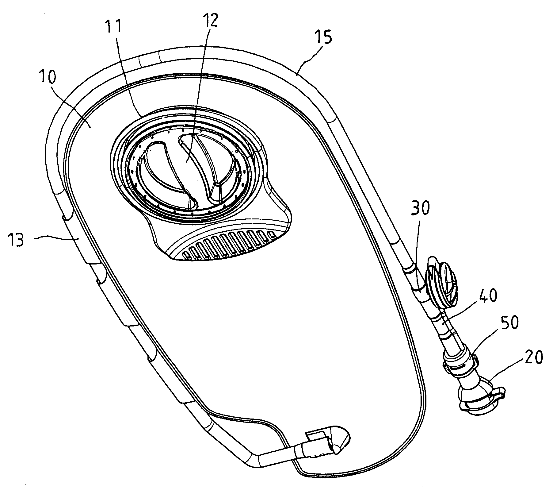
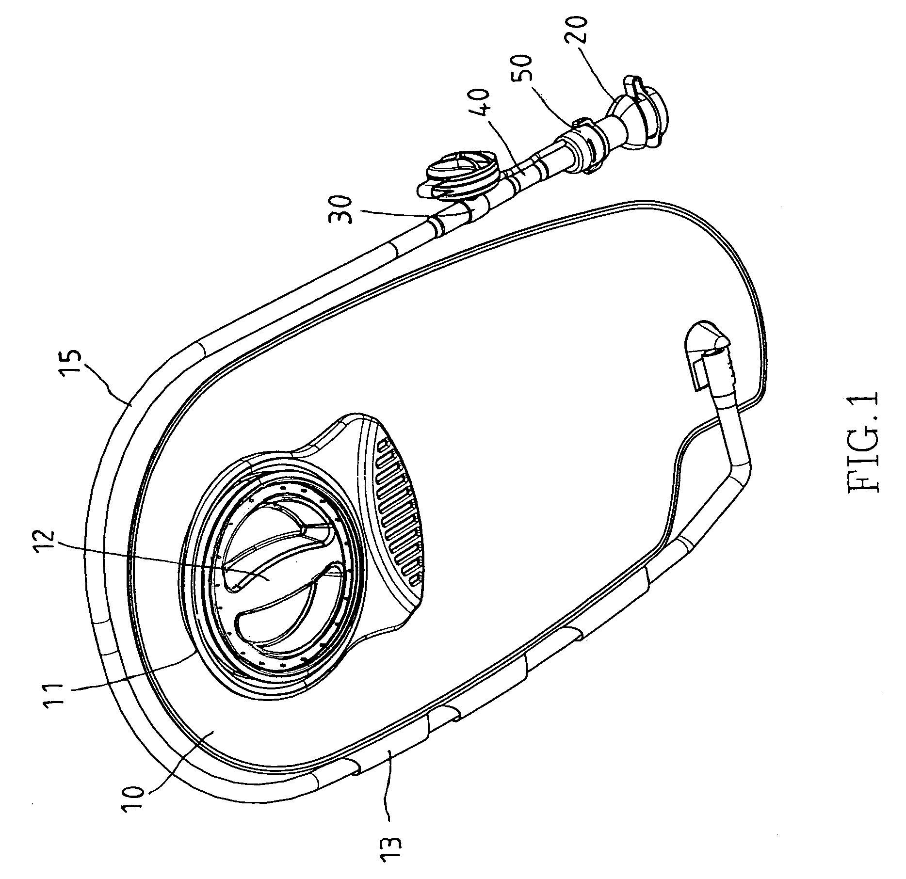
[0018]As shown in FIG. 1, a water bag of the preferred embodiment of the present invention includes:

[0019]A soft bag 10 has an intake 11.

[0020]A lid 12 covers the intake 11 to close or open the intake 11.

[0021]A hose 15 has an end connected to the bag 10. The bag 10 has three rings 13 on a side for the hose 15 passing through.

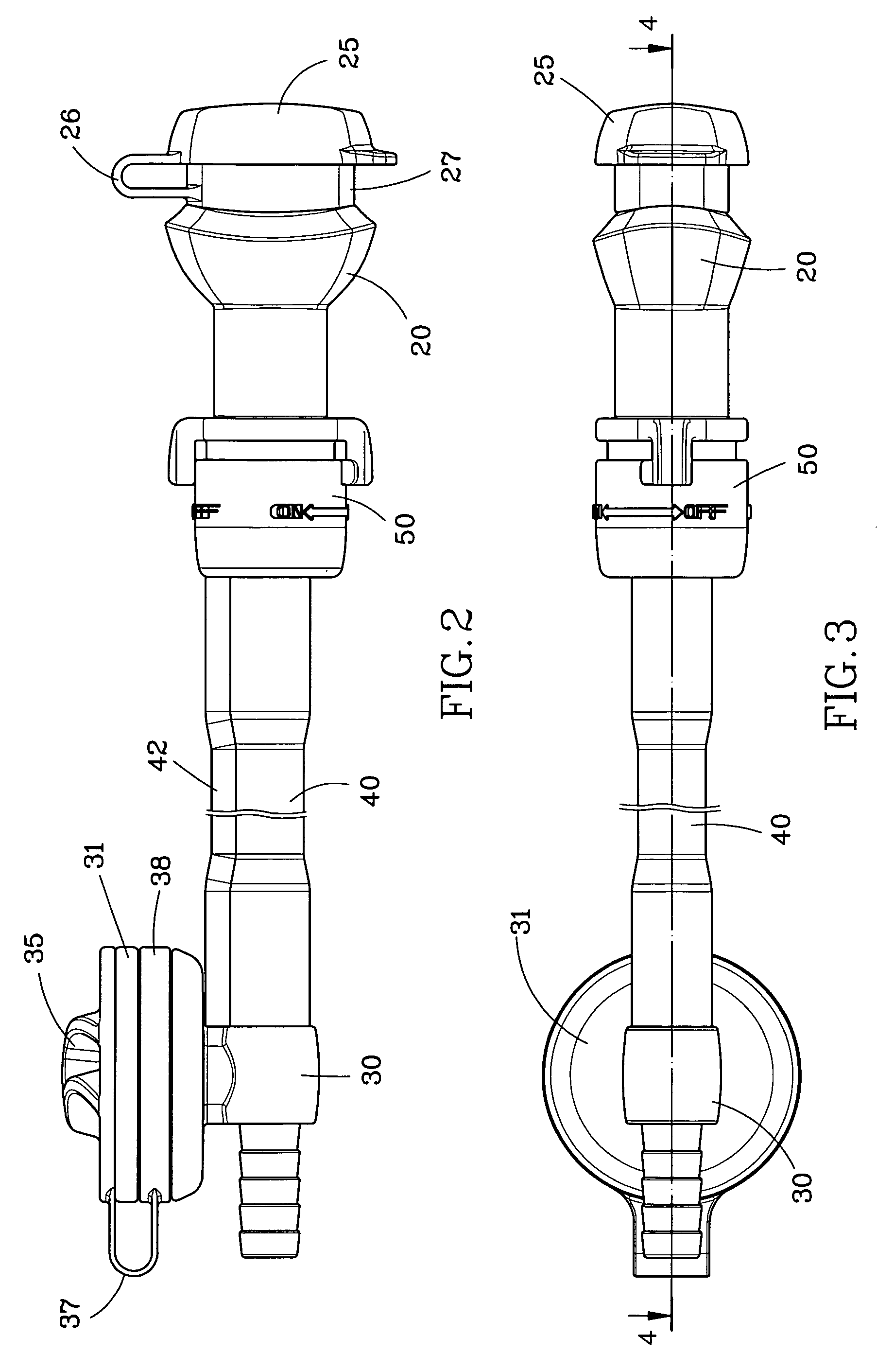
[0022]A mouthpiece 20 is connected to a free end of the hose 15.

[0023]A three-way valve 30 has a first end connected to the hose 15, a second end connected to the mouthpiece 20 and a third end forming a water inlet 31. On an interior wall of the water inlet 31 of the connector three-way 30, a threaded section 32 is provided. The water inlet 31 may be engaged with a common mineral water bottle, as shown in FIG. 7.

[0024]A cap 35 has a threaded section 36 to be screwed to a threaded section 32 of the water inlet 31. The cap 35 is provided with a strip 37 and a ring 38 on an end of the strip 37. The ring 38 is fitted to an annular slot 33 on the three-way valve 30 ...


PUM


Abstract

A water bag of the present invention includes a soft bag with an intake, a lid detachably covering the intake of the bag, a hose having an end connected to the bag and a mouthpiece connected to a free end of the hose. The hose has a water inlet to inject water into the soft bag and a cap detachably covering the water inlet. Therefore, water may be injected through the water inlet directly without having to take the soft bag out of the backpack.

Description

BACKGROUND OF THE INVENTION[0001]1. Field of the Invention[0002]The present invention relates generally a portable water bag, and more particularly to an intake structure of the water bag.[0003]2. Description of the Related Art[0004]Portable water bags are the common equipments of jogging, mountain-climbing, bicycle riding and so on. Typically, the conventional portable water bag includes a soft bag to be received in a backpack or in a specific pack. The bag has an intake to pour water into the bag, a lid to close the intake, a hose with an end connected to the bag, mouthpiece connected to a free end of the hose. People may suck water in the bag through the mouthpiece or just pour water on head or body to get cool. Such water bag is filled with water first, and then carried on back for drinking. If the water bag need to refill, people has to take the bag off, pour water into the bag, and then put it back to the backpack or specific pack. The refill action of the conventional water b...

Claims


Application Information

Patent Timeline
IPC IPC(8): B65D33/00B67D7/84
CPCA45F3/16A45F3/20A45F2003/166
Inventor WANG, LO-PIN
Owner WANG LO PIN
Why Eureka
Try Eureka