Al technical title is built by PatSnap Al team. It summarizes the technical point description of the patent document.
a capacitance sensing and capacitance technology, applied in the direction of electronic switching, pulse technique, instruments, etc., can solve the problems of stacking operational components and limited size of portable electronic devices
Active Publication Date: 2008-01-10
APPLE INC
View PDF99 Cites 322 Cited by
Summary
Abstract
Description
Claims
Application Information
AI Technical Summary
This helps you quickly interpret patents by identifying the three key elements:
Problems solved by technology
Method used
Benefits of technology
Problems solved by technology
In most cases, the size of the portable electronic device is limited by the size of the operational components used therein.
For thin devices such as cell phones, PDAs and media players, stacking operational components on top of each other is limited and therefore the operational components may be placed side by side.
Method used
Image
Click on the blue label to locate the original text in one second.
Reading with bidirectional positioning of images and text.
Examples
Embodiment Construction
[0034]The simplicity of capacitance allows for a great deal of flexibility in design and construction of the sensing device. By way of example, the sensing device may be based on self capacitance or mutual capacitance.
[0035]In self capacitance, each of the sensing points is provided by an individually charged electrode. As an object approaches the surface of the touch device, the object capacitively couples to those electrodes in close proximity of the object thereby stealing charge away from the electrodes. The amount of charge in each of the electrodes are measured by the sensing circuit to determine the positions of objects as they touch the touch sensitive surface.
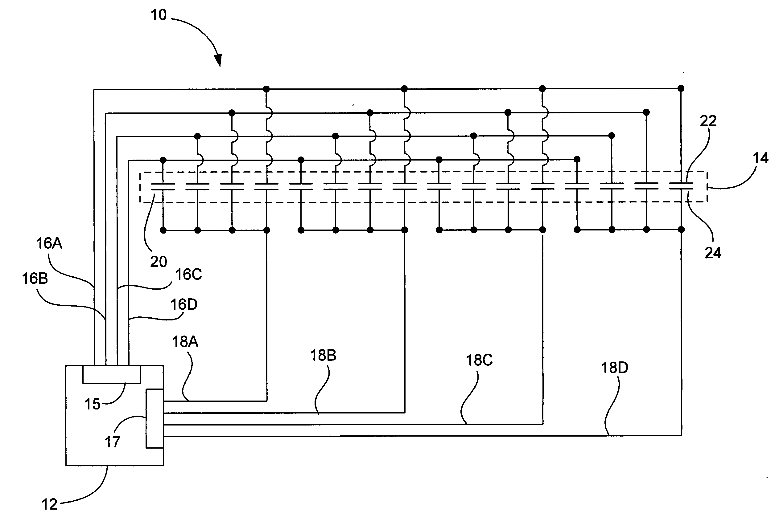
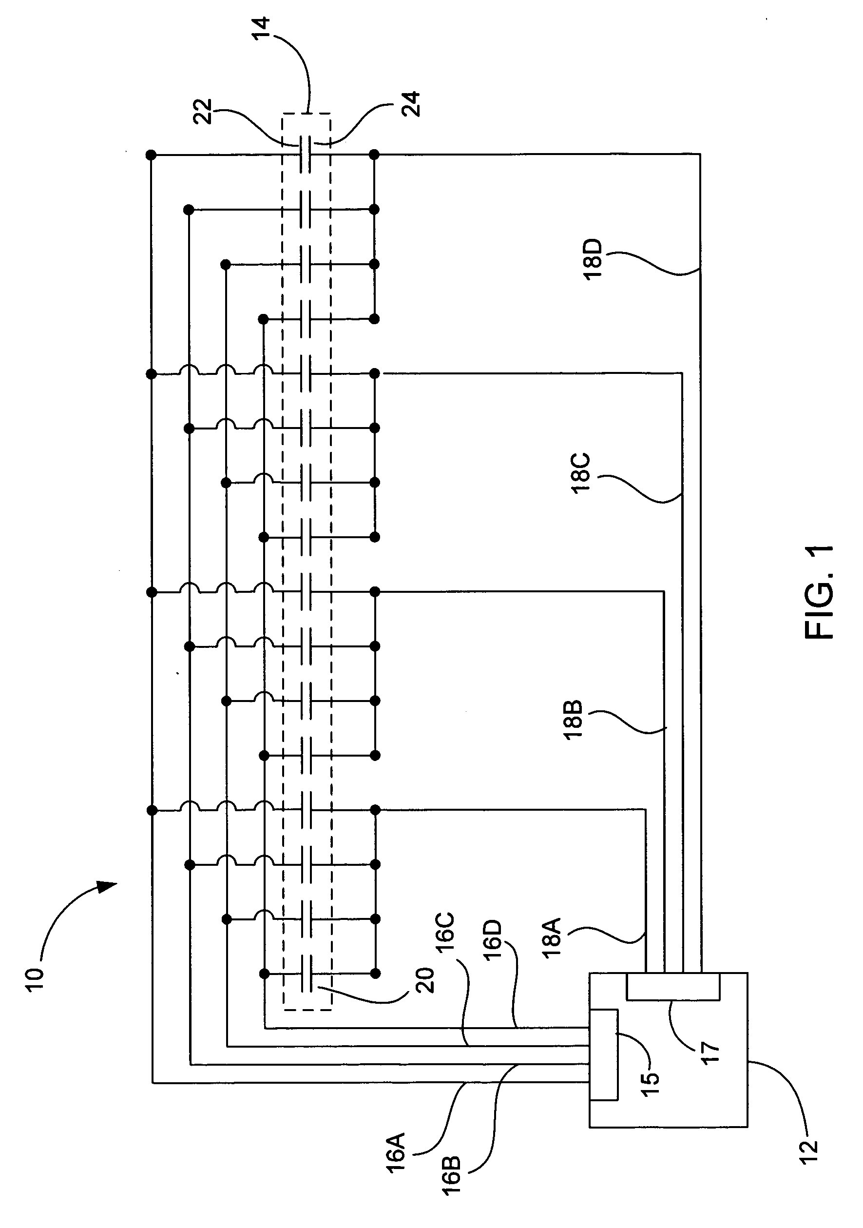
[0036]In mutual capacitance, the sensing device typically includes a two-layer grid of spatially separated wires. In the simplest case, the upper layer includes lines in rows while the lower layer includes lines in columns (orthogonal). The sensing points are provided at the intersections of the rows and columns. Durin...
PUM
Abstract
A mutual capacitive touch sensing device is disclosed. The touch sensing device includes a mutual capacitive sensing controller having a plurality of distinct drive lines and a plurality of distinct sense lines; a source for driving a current or voltage separately though each drive line; and a mutual capacitance sensing circuit that monitors the capacitance at the sensing lines. The touch sensing device also includes a plurality of independent and spatially distinct mutual capacitive sensing nodes set up in a non two dimensional array. Each node includes a drive electrode that is spatially separated from a sense electrode. The drive electrode is coupled to one of the drive lines and the sense electrode is coupled to one of the sense lines. Each node is set up with a different combination of drive and sense line coupled thereto.
Description
CROSS REFERENCE TO RELATED APPLICATIONS[0001]This application is related to the following applications, all of which are herein incorporated by reference:[0002]U.S. patent application Ser. No. 10 / 188,182, titled “TOUCH PAD FOR HANDHELD DEVICE”, filed Jul. 1, 2002; U.S. patent application Ser. No. 10 / 722,948, titled “TOUCH PAD FOR HANDHELD DEVICE”, filed Nov. 25, 2003; U.S. patent application Ser. No. 10 / 643,256, titled “MOVABLE TOUCH PAD WITH ADDED FUNCTIONALITY”, filed Aug. 18, 2003; U.S. patent application Ser. No. 10 / 840,862, titled “MULTIPOINT TOUCHSCREEN”, filed May 6, 2004; U.S. patent application Ser. No. 11 / 057,050, titled “DISPLAY ACTUATOR”, filed Feb. 11, 2005; and U.S. patent application Ser. No. 11 / 115,539, titled “HAND HELD ELECTRONIC DEVICE WITH MULTIPLE TOUCH SENSING DEVICES”.BACKGROUND OF THE INVENTION[0003]1. Field of the Invention[0004]The present invention relates generally to touch sensing devices used in portable electronic devices. More particularly, the presen...
Claims
Application Information
Patent Timeline
Application Date:The date an application was filed.
Publication Date:The date a patent or application was officially published.
First Publication Date:The earliest publication date of a patent with the same application number.
Issue Date:Publication date of the patent grant document.
PCT Entry Date:The Entry date of PCT National Phase.
Estimated Expiry Date:The statutory expiry date of a patent right according to the Patent Law, and it is the longest term of protection that the patent right can achieve without the termination of the patent right due to other reasons(Term extension factor has been taken into account ).
Invalid Date:Actual expiry date is based on effective date or publication date of legal transaction data of invalid patent.
Patent Type & Authority Applications(United States)